30
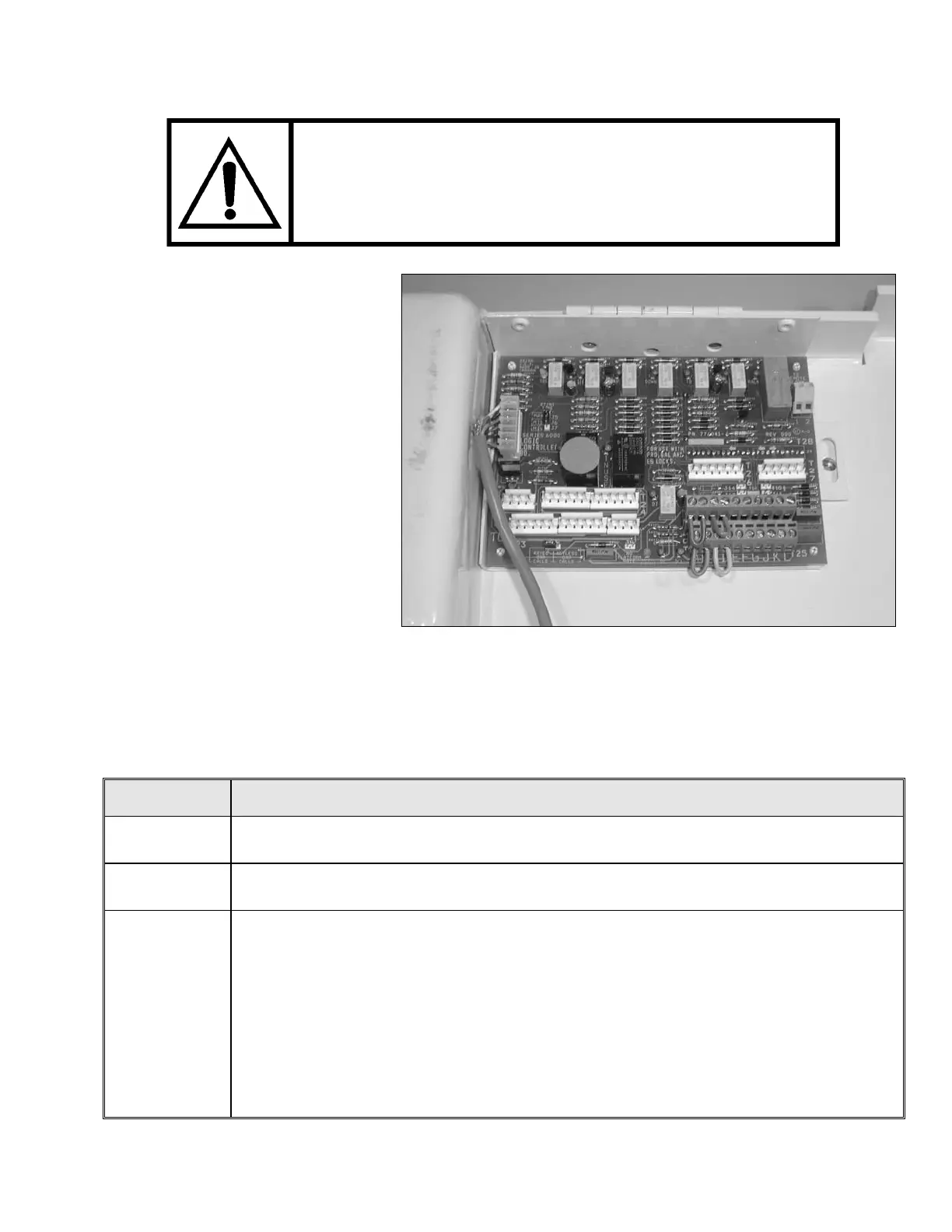
Figure # 19 Logic Control Board
JUMPERS (BRIDGES)
WIRING BRIDGES HAVE BEEN FACTORY INSTALLED
IRED
In order to opera
ilift prior to
oors, the
rs) are ins
ach floor. S
8 is to b
platform gate is
e Jump
gate is
tform gate
you must install J9 to
ate the platf
m landing a
ate the platf
ing.
. (LIGH
In sequence, the following LED’s should be “ON”.
AND MUST BE REMOVED ONCE THE GATES HAVE
BEEN INSTALLED AND THE GATE LOCKS ARE W
TO THE CONTROLLER.
te the Concord
Hand installing the
gates/d
(jumpe
wiring bridges
talled on
connections “A to B” and “C to D”
for e ee Figure # 19.
Jumper J e removed if a
to be installed. Do
not remov
platform
er J8 if no
to be used.
If pla is to be installed,
Jumper
oper
botto
orm gate at the
nd Jumper J10 to
oper orm gate at the top
land
L.E.D T EMITTING
DIODES)
L.E.D. DESCRIPTION/FUNCTION
PF
POWER FAILURE LED (green) is ON whenever 115 VAC is connected to the board
and it indicates that there is voltage after the transformer but before the rectifier.
POWER
POWER LED (green) indicates that there is 24 VDC through Fuse 2 to feed the safety
circuit.
SC
SAFETY CIRCUIT LED will be lit if the safety circuit is closed; thereby, indicating
that the Concord Handilift is “Ready” to travel (providing the limit switches, etc., are
all closed). If the Red LED ma ore of the following
the back up nut and the safety nut
switch has been opened,
b) The car stop button (if equipped) has been pressed,
c) The pit switch (if equipped) is OFF, or
d) The final limit (if equipped) has been opened.
rked “SC” is not lit, one or m
conditions may exist:
a) The main drive nut has failed and the unit is on