27
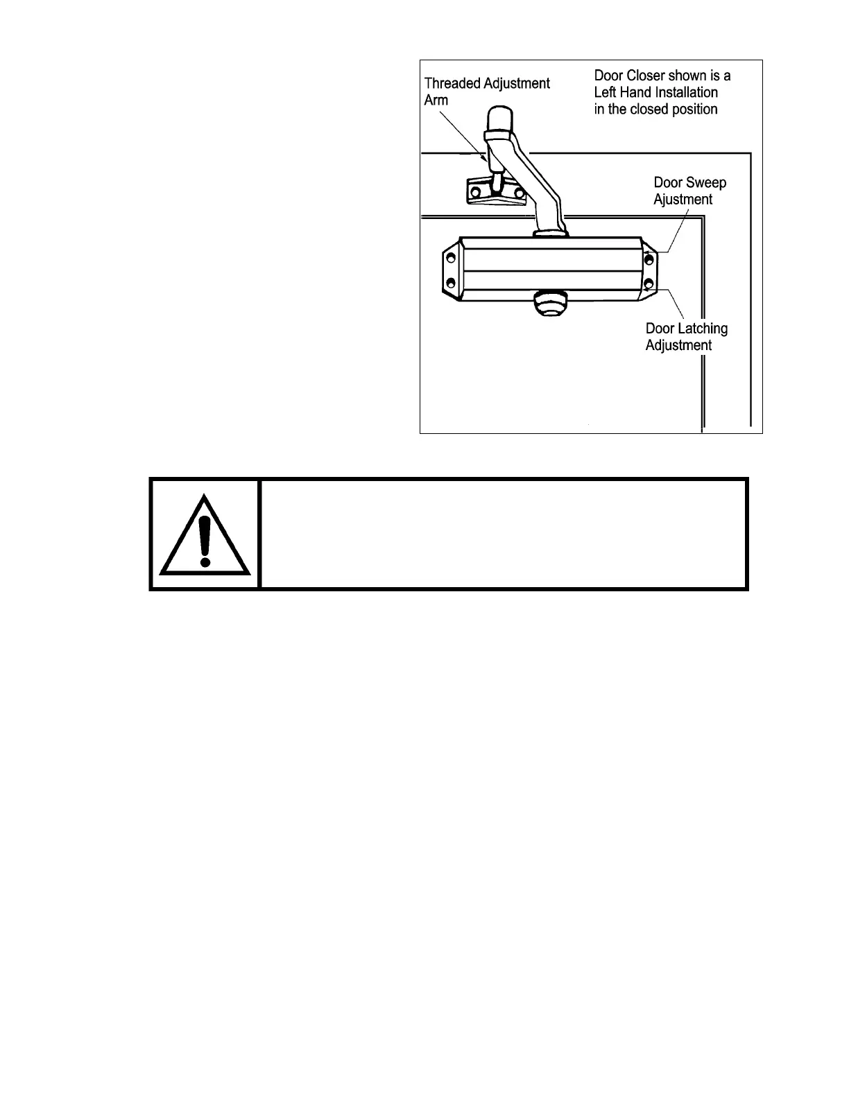
Figure # 16 Two-Speed Door Closer Set-Up
maintain the locking interlock beak
(keeper) within the beak housing.
The main sweep speed of the door starts at
To adjust the latching speed, set the
er. This
may vary slightly depending on the
witho
all
without slamming. The door must
be held closed with enough force to
the fully open position to 8" (203 mm) from
the fully closed position. The latching speed
of the door begins at 8" (203 mm) from fully
closed.
1)
adjusting arm on the clos
closure manufacturer.
2) Set the main sweep speed slow
enough to allow a disabled or
elderly person to enter the lift
ut the door striking them. The
latch speed should be slow enough
to ow the door to close firmly
TO PRE
TURN THE
VENT THE VALVE FROM DISLODGING, DO NOT
ADJUSTING VALVE MORE THAN TWO FULL
TURNS COUNTER- WISE FROM ITS FACTORY SET
crew counter-clockwise for a faster sweep speed.
2) To adjust “Latch” speed, turn speed-adjusting screw 2.
a) Turn the speed adjusting screw clockwise for a slower latch closing speed.
b) Turn the speed adjusting screw counter-clockwise for a faster latch closing speed.
SERVICE PANEL REMOVAL (4 FOOT UNITS)
To access the controllers, remove the front service panel of the Handilift unit. The panel is removed in
the following manner:
1) Grasp the removable service panel on each side through the slot openings.
2) Raise the panel as high as possible. Pull the bottom of the panel towards you while
standing on the carriage, until the panel can not be moved forward any further.
3) Lower the panel towards the ground until it exits the top retainer clips in the top cover.
4) The panel is now free to be raised up and out from the area between the carriage and the
tower.
CLOCK
POSITION. OTHERWISE, INTERNAL FLUID LOSS AND
DEVICE FAILURE MAY OCCUR.
1) To adjust “Sweep” speed, turn speed-adjusting screw 1.
a) Turn the speed adjusting screw clockwise for a slower sweep speed.
b) Turn the speed adjusting s