16
8) CONTROL WALL STABILIZER BRACKET
On SE (Semi-Enclosed) Units and units with a platform gate, a control wall stabilizer
bracket is supplied. The bracket has two clips that fit onto the Upper Threaded
Adjustment Rod. See Figure # 6. To install the platform, loosen the two (2) 1/2"
(13 mm) outside nuts and the two (2) 1/2" (13 mm) inside nuts on the Thread Adjustment
Rod. Slide the slotted clips onto the threaded adjustment rod. The clips fit between the
stiles and the inside nuts. Adjust the clips to the correct position and then tighten the
nuts. Measure and hold the critical distance, 20-5/16" (516 mm) inside-to-inside between
the stiles.
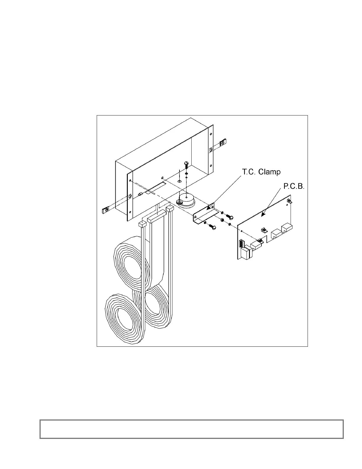
ove the car station plate to connect the traveling cable electrical "plugs" to the PCB in the car
e plug ends of
e traveling cable up through the hole provided in the bottom of the car station box. See Figure # 7.
oosen the traveling cable clamp first. Plug the Traveling Cable ends into the PCB and tighten the
etal traveling cable clamp, (as per Sheet 9 in Appendix A).
NOTE
Rem
station box. Uncoil the traveling cable from its shipping position on the sling. Insert th
th
L
m
Ensure that each plug (pin 1 on male and female) is correctly oriented.
Figure # 7 Travelling Cable and C.O.P.