19
NOTE
On 48" (1219 mm) long travel units, the ramp cam is pre-installed. On all other travel units, the
ramp cam must be installed in the field.
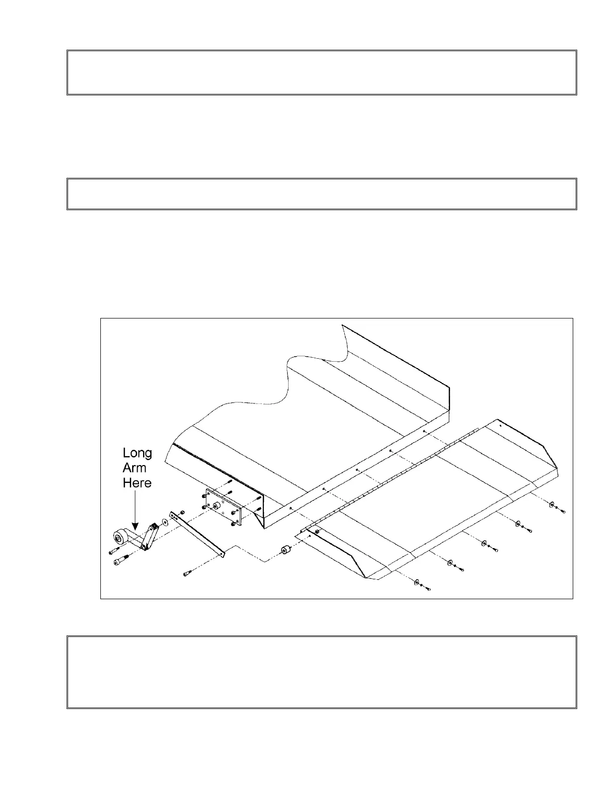
4) Place the side of the ramp cam so that the rounded edge is flush to the carriage side of
the tower. Lower the ramp cam until the beginning of the rounded edge touches the roller
wheel on the linkage-arm assembly. Check that the rounded edge side of the ramp cam
is flush with the carriage side of the tower, then mark the bolt hole locations.
NOTE
The cam has slotted holes and the marks should be made in the center of the slots.
5) To check the functioning of the ramp, operate the Handilift in the UP direction.
6) Ensure that the front of the ramp just touches the floor when the Handilift lowers and
stops. If the ramp is too high, adjust the down limit switch enough to bring the ramp to the
desired position at the lower level. Make sure the ramp gradient is sloped to permit easy
access into the lift.
NOTE
Figure # 10 Assembly of the Automatic Ramp
Check that the under-platform obstruction sensor pan does not activate when the platform is at
the lower level. To ensure correct ramp positioning at the lower level and the under-platform
obstruction sensor does not touch the floor, adjust the limit switch or lower the cam. Use the
slots provided. The limit switch should stop the lift, not the sensor.