2813
11
1. Close to a plain water inlet supply line with a minimum pressure of 12 psig.
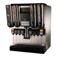
NOTE: “AIR-COOLED FCB DISPENSER
The “air-cooled” FCB Dispenser refrigeration system is equipped with a condenser coil that is cooled
by a condenser coil fan. Circulating air, required to cool the refrigeration system’s condenser coil, is
drawn in through grille on front and exhausted out through sides and back of Unit. Restricting air
circulation through the Unit will decrease its cooling efficiency.
2. When installing Unit, do not allow obstruction to block grille on front which will block off air intake to inside
of Unit. If installation dictates only one side or back being unobstructed, allow 18-inches clearance between
Unit and obstruction. If both sides or one side and back are unobstructed, allow 12-inches clearance. If
both sides and back are unobstructed, allow 6-inches clearance.
INSTALLING UNIT
PLACING UNIT IN OPERATING LOCATION
1. Place Unit in operating location meeting requirements of SELECTING LOCATION.
IMPORTANT NOTICE
The FCB Dispensers manufactured prior to the models documented in this manual were elevated in the front
(dispensing valve side) 1/4 to 3/8-inch higher than the back when placing the Unit in operating position to
eliminate gas pockets being trapped inside the freeze cylinders. Due to a re-design of the foam pack in the
models documented in this manual, elevating the front of the Dispenser is no longer required. The Dispenser
must be leveled at time of placing in operating location.
Note: An alternate to sealing the Unit base to the floor would be to install the 4-inch Caster Kit
provided with the Unit. Refer to installation Instructions provided with the kit for installation
instructions. .
2. After Unit has been placed in operating location, make sure it is sitting in a level position.
3. To comply with National Sanitation Foundation (NSF) requirements, Unit installed with base contacting floor
must have base sealed to floor with Dow Corning RTV 731 or equivalent.
INSTALLING DRIP TRAY SUPPORTS, DRIP TRAY, AND CUP REST
1. Install DRIP TRAY SUPPORTS (item 7) on panel above lower front access panel on front of Unit. Secure
supports to panel with THREAD CUTTING SCREWS (item 6).
2. Place DRIP TRAY (item 9) in FRAME, DRIP TRAY (item 8), then slide frame up on drip tray supports on
front of Unit.
INSTALLING DRIP TRAY DRAIN HOSE KIT
Install DRIP TRAY DRAIN HOSE KIT (item 10) on Unit as instructed in Installation Instructions provided with
the Kit.