Page 10
KEYPAD ADDRESS ASSIGNMENT
It is possible to connect up to 8 LCD keypads to the PW64 panel. By default, the keypad mounted inside the cabinet
is set to address number 1. If connecting additional keypads to the panel, ensure that each new keypad is addressed
separately to avoid conflicts on the keypad buss.
IMPORTANT NOTE: KEYPAD ADDRESS CHANGES ARE ONLY RECOGNISED AT POWER-UP. ALL CHANGES
SHOULD BE MADE IN THE POWERED DOWN STATE AND THEN ON POWER-UP THE NEW KEYPAD AD-
DRESS WILL BE RECOGNISED BY THE PANEL.
The 8 way switch on the LCD keypad is used to select the keypad address and the panel type that the keypad is con-
nected to. Please use the charts below when configuring extra keypads.
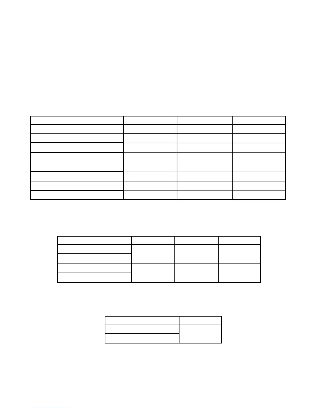
To assign the KEYPAD Address
Change the switches 1,2,3 according to the following table:
To assign the type of PowerWave Control Panel
Change the switches 5,6,7 according to the following table:
To set the Keypad tamper mode
Change switch 8 according to the following table:
Switch 1 Switch 2 Switch 3
Keypad # 1 OFF OFF OFF
Keypad # 2 ON OFF OFF
Keypad # 3 OFF ON OFF
Keypad # 4 ON ON OFF
Keypad # 5 OFF OFF ON
Keypad # 6
ON OFF ON
Keypad # 7
OFF ON ON
Keypad # 8 ON ON ON
Switch 5 Switch 6 Switch 7
PW-4 OFF OFF OFF
PW-8 ON OFF OFF
PW-16 OFF ON OFF
PW-64 ON ON OFF
Switch 8
Disable Keypad Tamper ON
Enable keypad Tamper
OFF