Page 6
INPUT CONFIGURATIONS (ZONE WIRING DETAILS)
The in addition to the 60 wireless zones, the PW64 has 3 separate programmable monitored analogue inputs,
2 x Programmable, multi-state detection inputs
1 x Programmable tamper input
Each input must be terminated with a short or the appropriate combination of end-of-line resistors,
depending upon the programmed configuration.
ZONE INPUTS - Each of the 2 hardwired zone inputs (Labelled 1+3 & 2+4) can be independently assigned one of
the following configuration options;
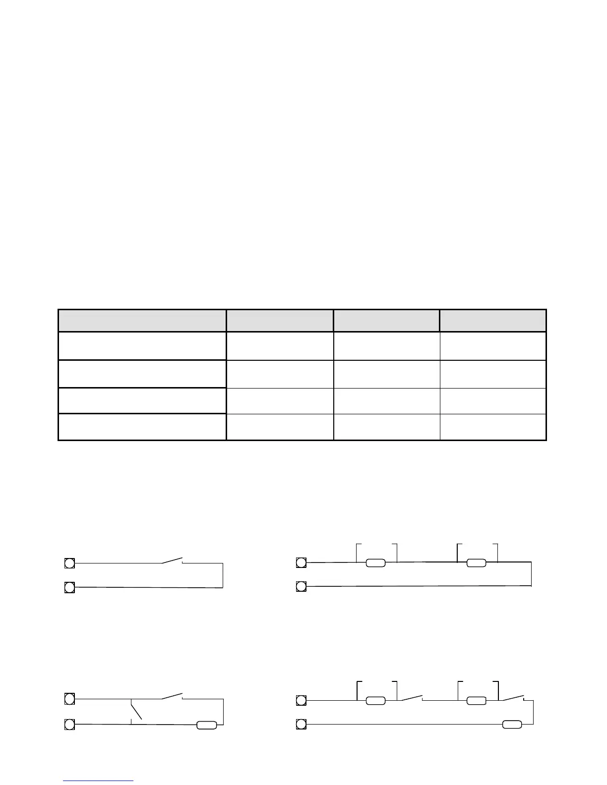
Type 1 Single Zone Short circuit input NO-End-of-Line (EOL).
Type 2 Single Zone End-of-Line 2k2 (EOL) with no tamper.
Type 3 Dual Zone Double-End-of-Line (EOL) No Tamper.
Type 4 Dual Zone Double-End-of-Line (EOL) With open & short circuit Tamper.
The following table shows end-of-line resistor configurations. The reference to LEDS in bold below relate to the
program option setting at addresses P601E & P602E. If the EOL option at address P601E is on then it relates to the
single zone being a 2K2 resistor but if zone doubling is turned on for the same input (P602E options 1&2) then EOL
means that the tamper resistor is 2K2. Without zone doubling, Input 1 = Zone 61 and Input 2 = Zone 62. If zone
doubling is selected zones 61 & 63 are on Input 1+3 and zones 62 & 64 are on input 2+4.
Zone Type Low Zone Hi Zone Tamper
Type 1
P601E LED 6 Off, P602E LED 1/2 Off
Loop (Short circuit) None None
Type 2
P601E LED 6 On, P602E LED 1/2 Off
2k2 None None
Type 3
P601E LED 6 Off, P602E LED 1/2 On
4k7 8k2 N/A
Type 4
P601E LED 6 On, P602E LED 1/2 On
4k7 8k2 2k2
Type 1 (Short Circuit)
n/c