Home
CubiScan
Measuring Instruments
125
Page 14 (Display and Output Options)
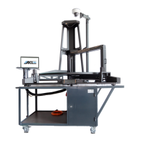
CubiScan 125 - Display and Output Options
96 pages
Manual
Save Page as PDF
To Next Page
To Next Page
To Previous Page
To Previous Page
Loading...
Product Des
cription
Specif
ications
CubiScan 125
4
Display:
Integrated TFT LCD touchscreen disp
lays length, width, height, weight,
unit of measure, 2D and height profile, and diagnostic codes.
Outputs:
Serial (1), Ethern
et (1), USB (1)
13
15
Table of Contents
Main Page
Default Chapter
6
Default Chapter
6
Table of Contents
6
Chapter 1 Product Description
11
Specifications
12
Chapter 2 Setup
15
Unpacking
15
Placement
16
Figure 2 Cubiscan 125 in Crate
16
Assembling the Cubiscan 125
17
Attaching the Top Sensor Support
18
Figure 3 Raised Screws at Top of Assembled Cubiscan 125
18
Attaching the Height Sensor Cable
19
Figure 4 Top Sensor Support Attached
19
Figure 5 Location of Height Sensor Cable
19
Figure 6 Routing the Height Sensor Cable
20
Figure 7 Attaching the Sensor Cable Cover
21
Figure 8 Connecting the Height Sensor Cable
22
Figure 9 Foam Shipping Supports
22
Removing the Shipping Material
22
Figure 10 Cable Tie Holding Measuring Gate
23
Figure 11 Glass Cubing and Weighing Platform
23
Placing the Glass Platform
23
Connecting Power
24
Turning on the Cubiscan 125
24
Figure 12 Connecting Power
24
Connecting to a Computer or Network (Optional)
25
Connecting to a Computer Via Ethernet
26
Figure 13 Ethernet, Serial, and USB Connectors
26
Figure 14 Installation Bubble
27
Figure 15 Device Installed Bubble
27
Figure 16 Installation Process Bubble
27
Figure 17 Adapter Is Ready to Use
27
Figure 18 Status Window
28
Connecting to a Computer Via USB
29
Figure 19 General Properties Window
29
Connecting to a Computer Via Serial (RS-232-C)
31
Installing Qbit (Optional)
31
Setup Checklist
31
Chapter 3 Operation
33
Before You Begin
33
Cubiscan 125 Touchscreen
34
Figure 20 Cubiscan 125 Touchscreen
34
Touchscreen Care
34
Cubing and Weighing
35
Cubing and Weighing Using Qbit
35
Cubing and Weighing Using the Touchscreen
35
Figure 21 Measurement Display
36
Figure 22 Package on Platform
37
Figure 23 Ultrasound Measurement Display
38
Figure 24 Measuring Gate
39
Figure 25 Measuring Gate Display
40
Figure 26 Height Display
40
Zeroing the Cubiscan 125
41
Chapter 4 Configuration
42
System Configuration
42
Operation
42
Figure 27 Home Screen
43
Figure 28 Configure Operation
43
Figure 29 Smallest Box Mode on
44
Figure 30 Smallest Box Mode off
45
Figure 31 Filter Mode on
46
Figure 32 Compression Mode
47
Units
48
Figure 34 Configure Operation
49
Ethernet
50
Figure 36 Configure Operation
51
Other
52
Figure 38 Configure Other
53
Chapter 5 Calibration
54
Before You Begin
54
Calibrating the Scale
55
Figure 40 First Scale Calibration Screen
56
Figure 41 Second Scale Calibration Screen
56
Figure 42 Second Scale Calibration Screen
57
Figure 43 Scale Calibration Complete
57
Calibrating the Gate
58
Figure 45 First Gate Calibration Screen
59
Calibrating the Touchscreen
60
Figure 46 Second Gate Calibration Screen
60
Figure 48 Touchscreen Calibration
61
Figure 47 Home Screen
61
Calibrating the Ultrasound Sensors
62
Figure 49 Touchscreen Calibration
62
Figure 50 Home Screen
63
Figure 51 First Sensor Calibration Screen
64
Figure 52 Second Sensor Calibration Screen
64
Figure 53 Third Sensor Calibration Screen
65
Figure 54 Fourth Sensor Calibration Screen
66
Figure 55 Fifth Sensor Calibration Screen
67
Figure 56 Sensor Calibration Complete
67
Chapter 6 Maintenance
68
Precautions
68
Cleaning the Ultrasound Sensors
68
Cleaning the Gate Filters
69
Removing the Controller
69
Figure 57 Control Box
70
Chapter 7 Troubleshooting
71
No Response When You Turn Power on
71
Scale Readings Are Not Accurate
72
Dimension Readings Are Not Accurate
72
Computer Error Messages
72
About
73
Version
73
Figure 58 Home Screen
74
Figure 59 about Version
74
Config-Audit
75
Cal-Audit
76
Figure 61 about Config-Audit
76
Figure 62 Home Screen
77
Figure 63 about Cal-Audit
77
Diagnostics
78
Scale Diagnostics
78
Figure 65 Scale Diagnostics
79
Gate Diagnostics
79
Figure 66 Home Screen
80
Figure 67 First Gate Diagnostic Screen
81
Figure 68 Second Gate Diagnostic Screen
82
Figure 69 Gate Mask Tick Marks
83
Figure 70 Third Gate Diagnostic Screen
84
Touchscreen Diagnostics
84
Figure 71 Home Screen
85
Figure 72 Diagnostic Touchscreen
86
Sensor Diagnostics
86
Figure 73 Home Screen
87
Figure 74 Diagnostic Sensors
88
Testing
89
Scale
89
Gate
90
Figure 77 Home Screen
91
Figure 78 First Gate Test Screen
92
Parts List
94
Figure 80 Parts List
95
Appendix A Parts List.
96
Firmware Log
96
Other manuals for CubiScan 125
Quick Reference Guide
2 pages
Related product manuals
CubiScan 100-T
2 pages