CBX ELECTRICAL CONNECTIONS
21
3
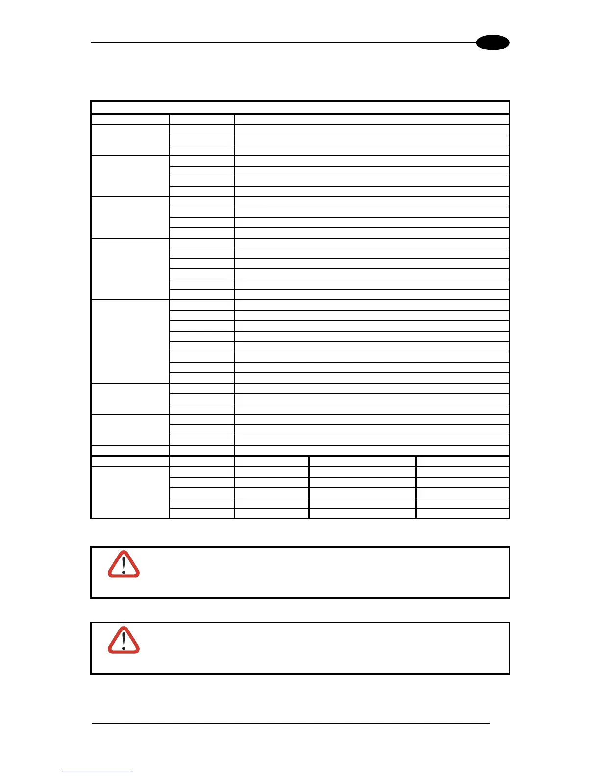
The table below gives the pinout of the CBX100/500 terminal block connectors. Use this
pinout when the DS6300 reader is connected by means of the CBX100/500:
CBX100/500 Terminal Block Connectors
Group Name Function
Vdc Power Supply Input Voltage +
GND Power Supply Input Voltage -
Input Power
Earth Protection Earth Ground
+V Power Source – External Trigger
I1A External Trigger A (polarity insensitive) for PS
I1B External Trigger B (polarity insensitive) for PS
External Trigger
(PS) Input
-V Power Reference – External Trigger
+V Power Source – Inputs
I2A Input 2A (polarity insensitive) for Encoder
I2B Input 2B (polarity insensitive) for Encoder
Encoder or
Generic Input
-V Power Reference – Inputs
+V Power Source – Outputs
-V Power Reference – Outputs
O1+ Output 1+
O1- Output 1-
O2+ Output 2+
Outputs
O2- Output 2-
O3A Output 3A (polarity insensitive)
O3B Output 3B (polarity insensitive)
+V Power Source – Other I/O
I3A Input 3A (polarity insensitive)
I4A Input 4A (polarity insensitive)
-V Power Reference – Other I/O
I34B Input 3B and 4B (common) (polarity insensitive)
Other I/O
(CBX500 only)
I34B Input 3B and 4B (common) (polarity insensitive)
TX Auxiliary Interface TX
RX Auxiliary Interface RX
Auxiliary Interface
SGND Auxiliary Interface Reference
REF Reserved
ID+ Reserved
ID-NET™
ID- Reserved
Network
Shield Network Cable Shield
RS232 RS485FD RS485HD
TX TX+ RTX+
RTS TX- RTX-
RX *RX+
CTS *RX-
Main Interface
SGND SGND SGND
* Do not leave floating, see par. 3.2.2 for connection details.
CAUTION
Do not connect GND and SGND to different (external) ground references.
GND and SGND are internally connected through filtering circuitry which
can be permanently damaged if subjected to voltage drops over 0.8 Vdc.
CAUTION
DS6300 scanners do not support Host Interface Modules with the CBX500.
Use the CBX800 Gateway for Host Interface Applications, (Fieldbus and
non Fieldbus).