DS6300 REFERENCE MANUAL
32
3
3.4.1 Code Verifier
If the DS6300 is used as a Code Verifier, the verifier code can be configured in software
through the Genius™ configuration program. However it is also possible to use one of the
inputs to trigger when the scanner should store a code read as the verifier code.
The Code Verifier parameter must be enabled, and the configuration parameters to allow
correct Code Type reading must be saved to the scanner in order to read the verifier code.
When the selected input is activated, the next read code will be stored as the verifier code in
the scanner's non-volatile (Flash) memory.
For more details see the Verifier Parameters in the "6-8 K Software Configuration Parameter
Guide” or Help file.
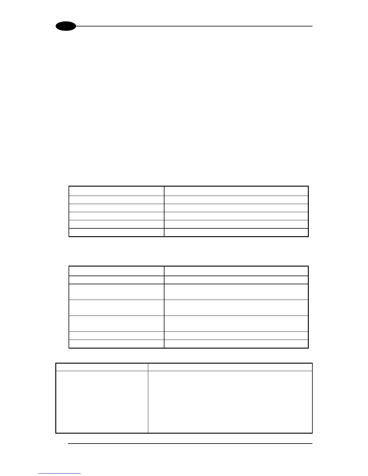
3.5 OUTPUTS
Three general purpose outputs are available. The electrical features are given below:
Outputs 1 and 2
Maximum Voltage 30 V
Collector Current (pulse) 130 mA Max.
Collector Current (continuous) 40 mA Max.
Saturation Voltage (VCE) 1 V at 10 mA Max.
Maximum Power Dissipation 90 mW at 50°C (Ambient temperature)
Output 3 has different electrical features. It is a bi-directional solid state relay with built-in
current limit protection.
Output 3
Maximum Voltage ± 100 V (Vext only)
Collector Current (pulse) 300 mA Max. at 25°C (Ambient temperature)
240 mA Max. at 50°C (Ambient temperature)
Collector Current (continuous) 200 mA Max. at 25°C (Ambient temperature)
150 mA Max. at 50°C (Ambient temperature)
R on
R off
6 – 15 Ω
> 500 Ω
Off-State Leakage Current < 1 µA
Maximum Power Dissipation 550 mW at 50°C (Ambient temperature)
CBX100/500
Function
+V Power Source - Outputs
O1+ Output 1 +
O1- Output 1 -
O2+ Output 2 +
O2- Output 2 -
O3A (CBX500 only) Output 3 A (polarity insensitive)
O3B (CBX500 only) Output 3 B (polarity insensitive)
-V Power Reference Outputs