CUSTOM CABLE ELECTRICAL CONNECTIONS
39
4
4.2.1 RS232 Interface
The main serial interface is used for communication with the Host computer and allows both
transmission of code data and configuring the reader. The overall maximum cable length
should not exceed 15 m (50 ft).
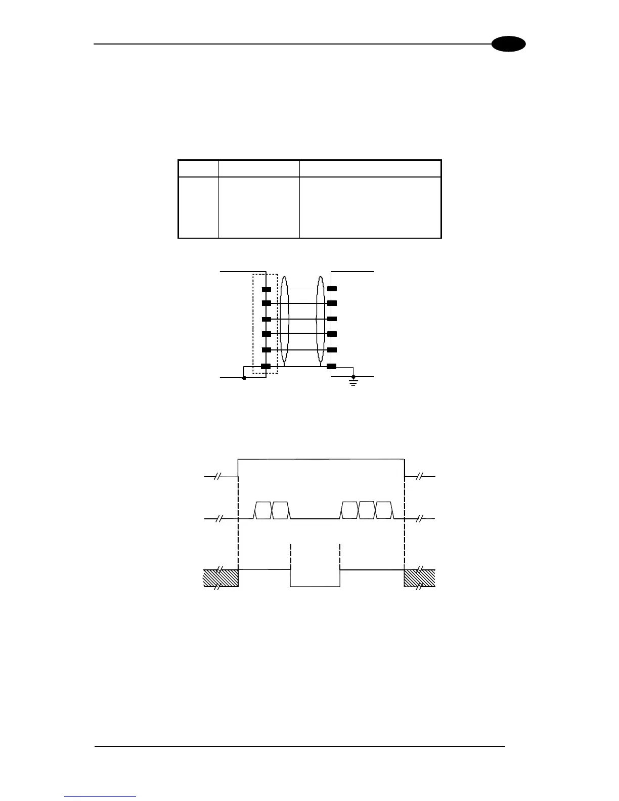
The following pins of the 25/26-pin connector are used for RS232 interface connection:
Pin Name Function
2 TX Transmit
3 RX Receive
4 RTS Request to send
5 CTS Clear to send
7 GND_ISO Main signal ground
DS
00
7 GND_ISO
SGND Main Isolated
USER INTERFACE
RTS4
CTS
5
RX3
RXD
TX2
TXD
1
Earth
Ground
CHASSIS
Figure 54 - RS232 Connections
START
OF
TRANSMISSION
END
OF
TRANSMISSION
+ V
RTS
- V
+ V
TX DATA
- V
+ V
CTS
- V
DATA
TRANSMISSION
DATA
TRANSMISSION
C1
C2
C4
C3
C5
TRANSMISSION
STOPPED
ENABLED
DISABLED
ENABLED
IDLE
IDLE
Figure 55 - RS232 Control Signals
The RTS and CTS signals control data transmission and synchronize the connected devices.
If the RTS/CTS handshaking protocol is enabled, the DS6300 activates the RTS output to
indicate a message is to be transmitted. The receiving unit activates the CTS input to enable
the transmission.