DS6300 REFERENCE MANUAL
28
3
3.4 INPUTS
There are four optocoupled polarity insensitive inputs available on the scanner: Input 1
(External Trigger/PS), Input 2 (Encoder), Input 3 and 4 generic inputs.
The electrical features of the inputs are:
Maximum voltage: 30 Vdc
Maximum current Input 1 and 2: 12 mA (scanner) + 12 mA (CBX)
Maximum current Input 3 and 4: 12 mA (scanner)
CBX100/500
Function
+V Power Source - External Trigger
I1A External Trigger A (polarity insensitive) for PS
I1B External Trigger B (polarity insensitive) for PS
I2A Input 2 A (polarity insensitive) for Encoder
I2B Input 2 B (polarity insensitive) for Encoder
I3A (CBX500 only) Input 3 A (polarity insensitive)
I4A (CBX500 only) Input 4 A (polarity insensitive)
I34B (CBX500 only) Common Reference for Inputs 3 and 4 (polarity insensitive)
-V Power Reference - External Trigger
The active state of all the inputs is selected in software (open or closed). Refer to the
Genius™ Help On Line.
All inputs are optocoupled, polarity insensitive, and driven by a constant current generator;
the command signal is filtered through an anti-disturbance circuit which generates a
debouncing delay which can be set to 5 ms or 500 s. In particular, I1 for PS, I3 and I4 share
the same value which usually corresponds to 5 ms when using a photoelectric sensor, while
I2 is set to 500 s when this input is used for the Encoder. The maximum Encoder frequency
is 2 kHz.
Input 1 (External Trigger/PS) is used in the On-Line operating Mode and tells the scanner to
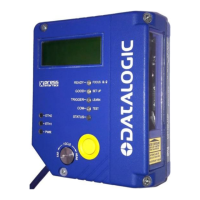
scan for a code. The yellow Phase On LED (Figure C, 3) which refers to Input 1 is on only
when current flows through the input circuit and t
herefore when the active state of this input
is set to "active open", the LED lights up when the input corresponds to OFF.
Input 2 is normally used for the Encoder input. The Encoder detects the conveyor speed.
Inputs 3 and 4 can be used as the stop signal for the reading phase.
The debouncing delay value can be changed through the software parameter Debouncing for
Input x, see the "6-8 K Software Configuration Parameter Guide” or Help file.
Powering Inputs
Input devices can be supplied by either scanner power (V+ and V-) or external power
supplies (Vext).
Electrical isolation between the input command logic and the scanner is maintained when
powering the input devices from an external supply voltage (Vext).
 Loading...
