CBX ELECTRICAL CONNECTIONS
29
3
The driving logic of the input signals may be powered, for convenience, with the voltage
supply at the CBX terminal block spring clamps (V+) and (V-). In this case, however, the
device is no longer electrically isolated. The voltage available on pins V+ and V-, is physically
the same as the input power for the scanner (Vdc and GND).
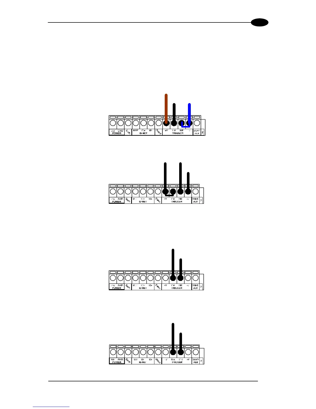
INPUT 1 (EXTERNAL TRIGGER/PS) CONNECTIONS USING DS6300 POWER
(brown)
(b lack) (b lue)
MEP-593 PH-1 Photocell (PNP)
Figure 32 – MEP-593 PH-1 (PNP) External Trigger/PS Using DS6300 Power
Power to In put
Photocell Signal
Photocell
Reference
NPN Photocell
Figure 33 - NPN External Trigger/PS Using DS6300 Power
INPUT 1 (EXTERNAL TRIGGER/PS) CONNECTIONS USING EXTERNAL POWER
External Device
Ground Reference
Input
Signal
Figure 34 - PNP External Trigger/PS Using External Power (i.e. PLC signal)
External Device
Power Ref erence
Input
Signal
Figure 35 - NPN External Trigger/PS Using External Power (i.e. PLC signal)