FIELDBUS CONNECTIONS
57
6
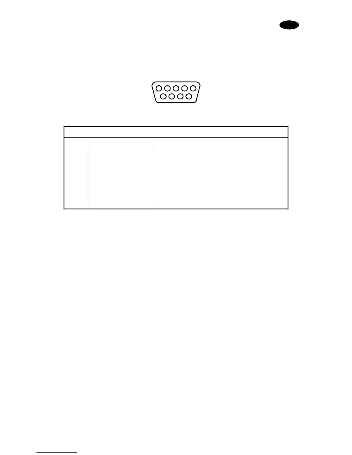
6.4 PROFIBUS INTERFACE
The 9-pin Profibus female connector (white) is only available in the DS6300 Profibus model
and allows connection between the host and the reader:
5
1
9
6
Figure 82 - Profibus 9-pin Female Connector
DS6300 9-pin Profibus connector pinout
Pin Name Function
1 Shield* Shield, Protective Ground resp.
2 Free
3 B-LINE (RxD/TxD-P) Received/Transmitted Data-P
4 CNTR-P** Repeater Control Signal
5 DGND Data Ground (M5V)
6 +5 V Voltage Plus (P5V)
7 Free
8 A-LINE (RxD/TxD-N) Received/Transmitted Data
9 CNTR-N** Repeater Control Signal
* signal is optional
** signal is optional; RS485 level
The Profibus interface is used for communication with an Host and allows expanding the
networking and remote diagnostic capabilities of the scanner.
For further details refer to the “Profibus_Fam6k.pdf” document provided as supplementary
documentation.