DS6300 REFERENCE MANUAL
56
6
6.3 DEVICENET INTERFACE
NOTE
When using DeviceNet, the Main serial interface is disabled and must not
be physically connected.
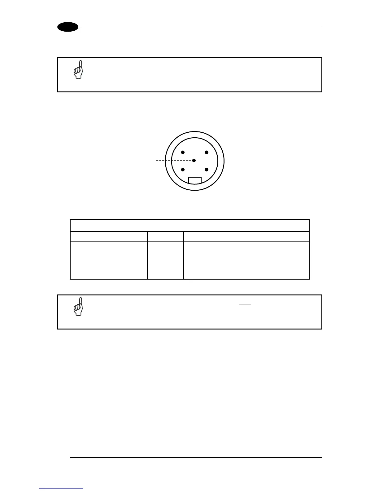
The 5-pin male connector is only available in the DS6300 DeviceNet model and allows
connection between the host and the reader:
1
3
2
4
5
Figure 81 - DeviceNet 5-pin Male Connector
DS6300 5-pin DeviceNet connector pinout
Pin Name Function
2 V + Supply voltage – positive pin
5 CAN_L CAN bus data line – L
1 SHIELD Shield
4 CAN_H CAN bus data line – H
3 V - Supply voltage – negative pin
NOTE
The power supplied on pin V+ and V- is used only
to propagate power to
the section of the DeviceNet board directly connected to the Bus. It is
completely isolated from the DS6300 power which must be supplied on pin
9, 13 and pin 23, 25 of the 26-pin Main/Aux connector.