CUSTOM CABLE ELECTRICAL CONNECTIONS
37
4
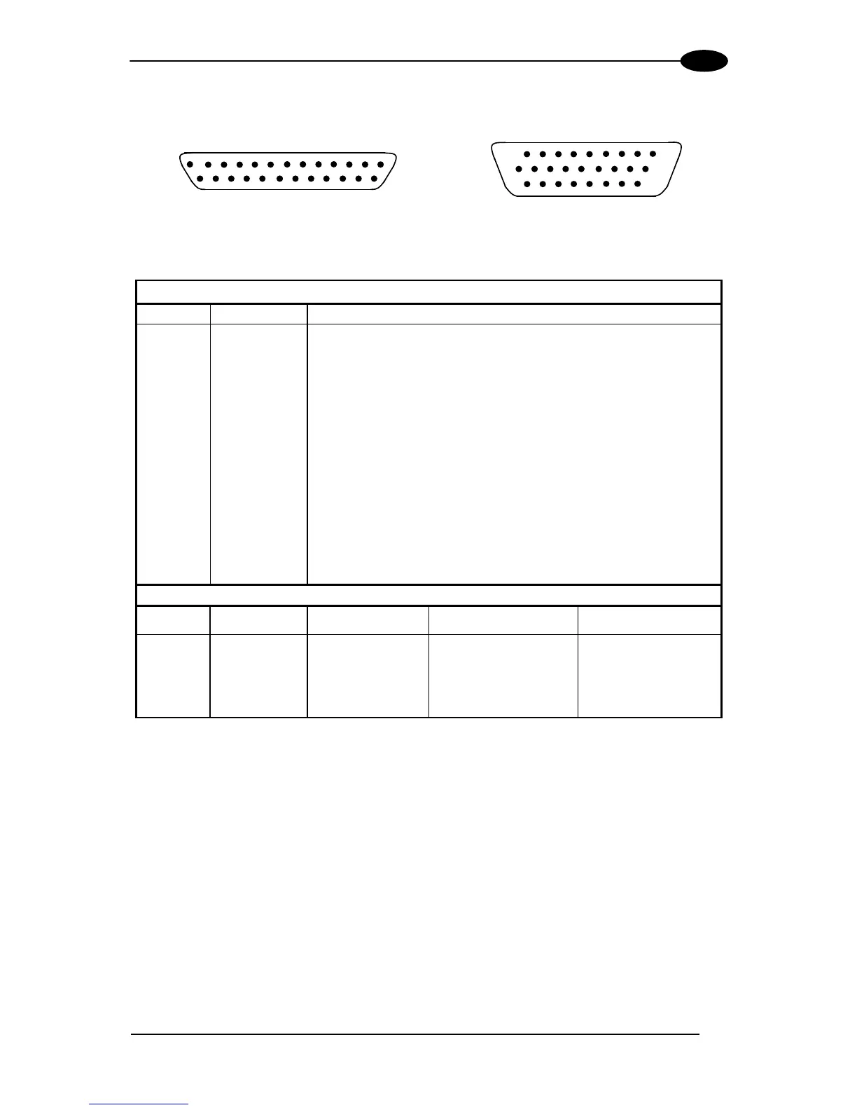
The details of the connector pins are indicated in the following table:
14
1
25
13
10
19
1
18
9
26
Figure 51 - 25-pin Connector Figure 52 - 26-pin Connector
DS6300 25/26-pin D-sub Connector Pinout
Pin Name Function
Chassis - internally connected to GND
1 CHASSIS
Cable shield connected to chassis
20 RX Receive Data of Auxiliary RS232 (referred to GND)
21 TX Transmit Data of Auxiliary RS232 (referred to GND)
8 O1+ Configurable Digital Output 1 - positive pin
22 O1- Configurable Digital Output 1 - negative pin
11 O2+ Configurable Digital Output 2 - positive pin
12 O2- Configurable Digital Output 2 - negative pin
16 O3A Configurable Digital Output 3 - polarity insensitive
17 O3B Configurable Digital Output 3 - polarity insensitive
18 I1A External Trigger (polarity insensitive) for PS
19 I1B External Trigger (polarity insensitive) for PS
6 I2A Input Signal 2 (polarity insensitive) for Encoder
10 I2B Input Signal 2 (polarity insensitive) for Encoder
14 I3A Input Signal 3 (polarity insensitive)
15 I4A Input Signal 4 (polarity insensitive)
24 I34B Common reference of Input 3 and Input 4 (polarity insensitive)
9,13 Vdc Power Supply Input Voltage +
23,25,26 GND Power Supply Input Voltage -
Main Interface Connector Pinout
Pin
RS232
RS485
Full Duplex
RS485
Half Duplex
2 TX TX+ RTX+
3 RX *RX+
4 RTS TX- RTX-
5 CTS *RX-
7 GND_ISO GND_ISO GND_ISO
* Do not leave floating, see par. 4.2.2 for connection details.
Pin 26 is only available for Fieldbus (Ethernet, DeviceNet, or Profibus) models.