Adjustments and Maintenance
2-30
6. Wait briefly. After READY is displayed, press FEED (to temporarily enable the voltage).
Adjust the voltage using RP1 on the Power Supply PCB according to the resistance range
listed in the appropriate table below.
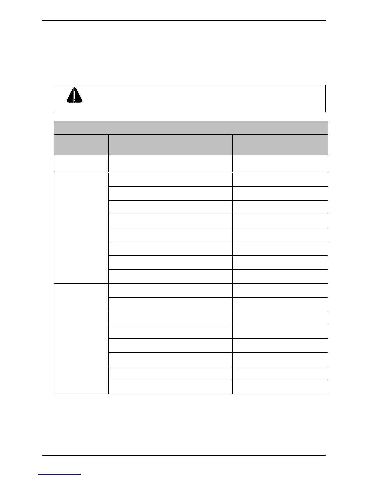
WARNING
Over-voltage can permanently damage or shorten printhead service life.
Printhead Voltage Adjustment
Model
Printhead Resistance
(Ohms)
Applied Voltage
(+/- 0.1 VDC)
M-4206 800 24.0
680 – 710 22.4
711 – 740 22.9
741 – 770 23.4
771 – 800 23.8
801 – 830 24.2
831 – 860 24.7
861 – 890 25.1
M-4210
891 – 920 25.5
953 – 994 22.4
995 – 1036 22.9
1037 – 1078 23.4
1079 – 1121 23.8
1122 – 1163 24.2
1164 – 1205 24.7
1206 – 1247 25.1
M-4306
1248 – 1289 25.5
7. Turn OFF and unplug the printer. Remove the multi-meter probes and reinstall the
covers.

 Loading...