Removal and Replacement
4-6
Installation:
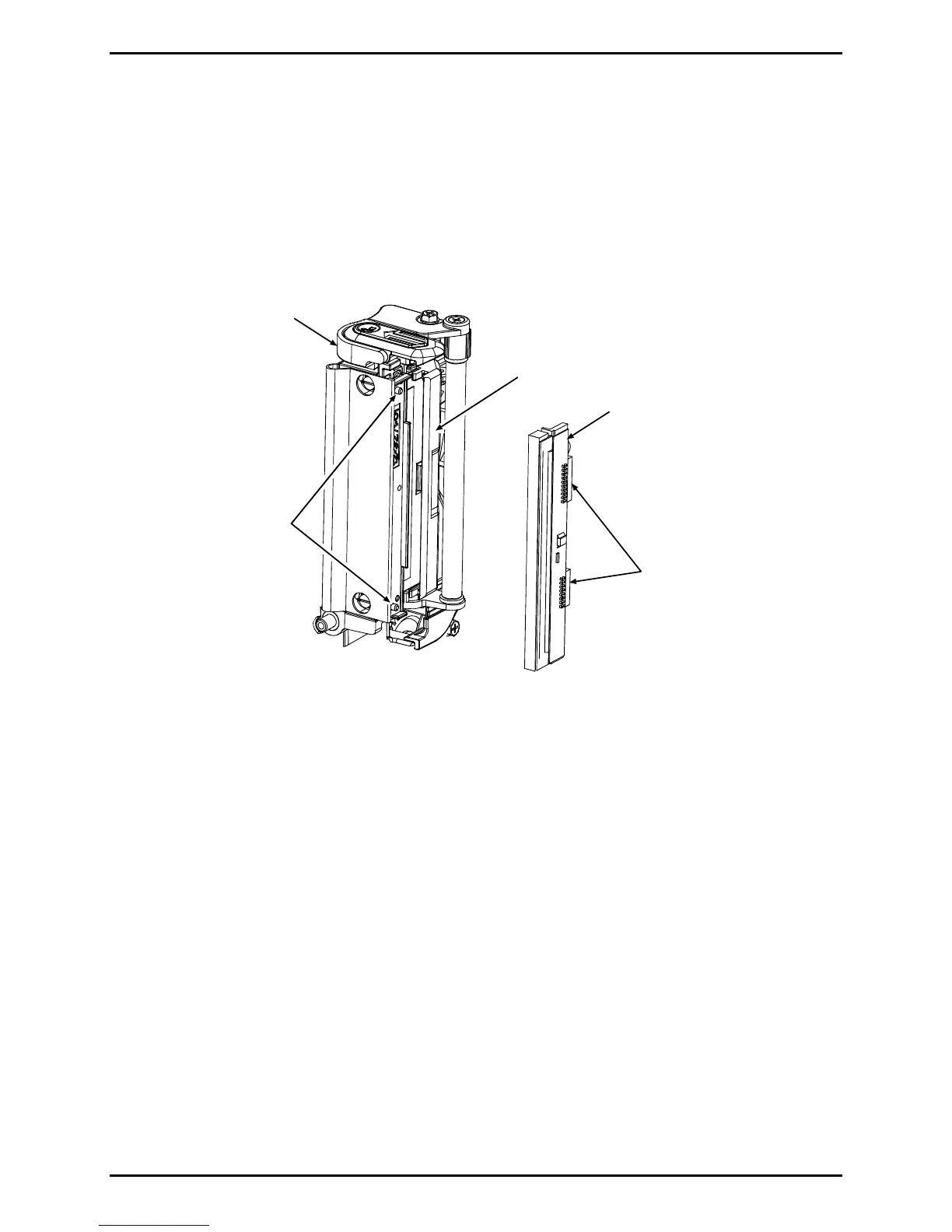
1. While carefully holding the Printhead, connect both cables.
2. Carefully slide the Printhead under the Guard and onto the Locator Pins in the Printhead
Assembly. Secure the Printhead with the Printhead Mounting Screw (do not over-
tighten).
Printhead
Printhead
Assembly
Cable
Connectors
Locator
Pins
Guard
3. Clean the Printhead; see Section 2.1.1.
4. Reload ribbon (if removed) then lower and latch the Printhead Assembly.
5. Adjust the darkness; see Section 2.7.
4.3.1 Printhead Assembly
Removal:
1. Remove the Side Cover Assembly (see Section 4.1) and the Front Cover (see Section
4.2).
2. Remove the Printhead; see Section 4.3.
3. Remove the Drive Gear Screw, Idler Post, and Drive Gear from the Centerplate.

 Loading...