Removal and Replacement
4-13
4.5 Power Supply PCB
Removal:
1. Turn OFF and unplug the printer.
2. Remove the Side Cover Assembly;
see Section 4.1.
3. Remove all cables connected to the
Power Supply PCB.
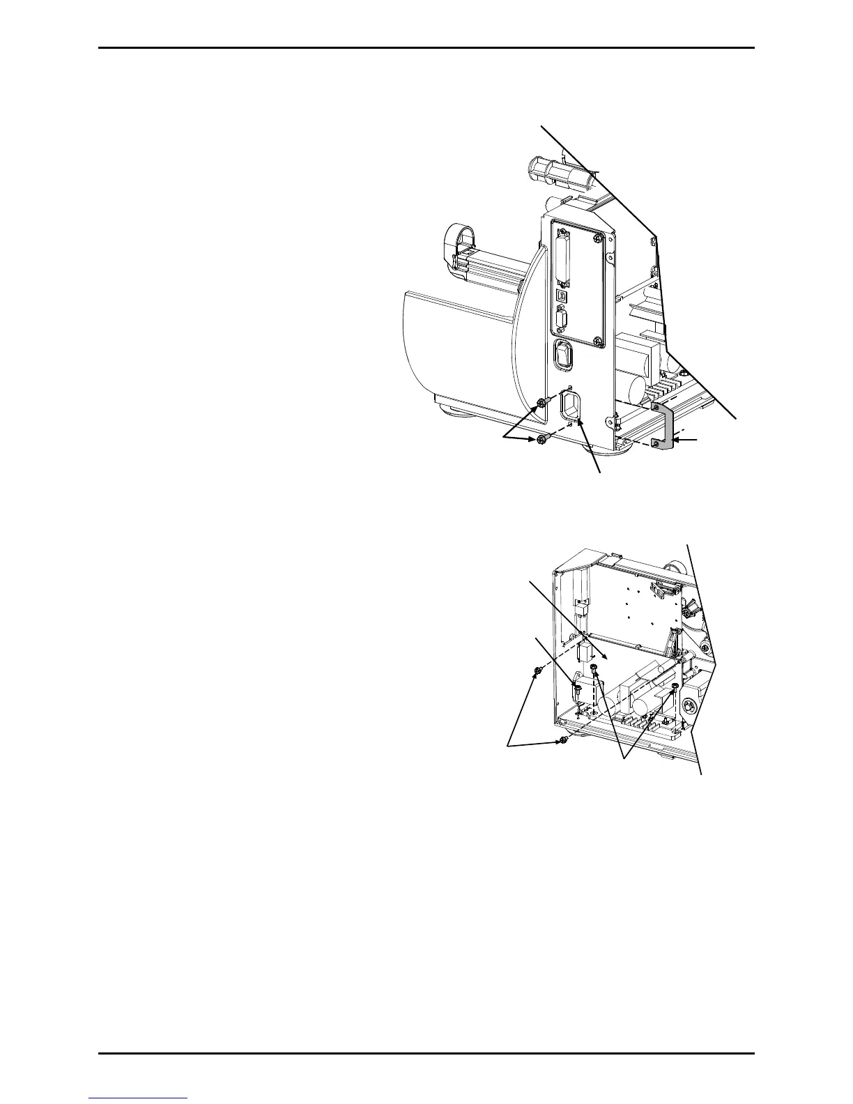
4. Remove the two Screws that secure
the AC Input Connector and Retainer
to the printer.
Screws
AC Input
Connector
AC Input
Retainer
5. Remove the Screw (and Lock
Washer) that secures the Ground
Wire.
6. Remove the two Short Screws that
secure the Power Supply PCB and
the two Long Screws that secure the
Power Supply Heatsink to the
printer.
Long
Screws
Short
Screws
Ground Screw/
Ground Wire
Power
Supply
PCB
7. Remove the Power Supply PCB from
the printer.
Installation:
1. Position the Power Supply PCB in the printer and secure it using the two Short Screws
(PCB) and the two Long Screws (Heatsink).

 Loading...