Removal and Replacement
4-15
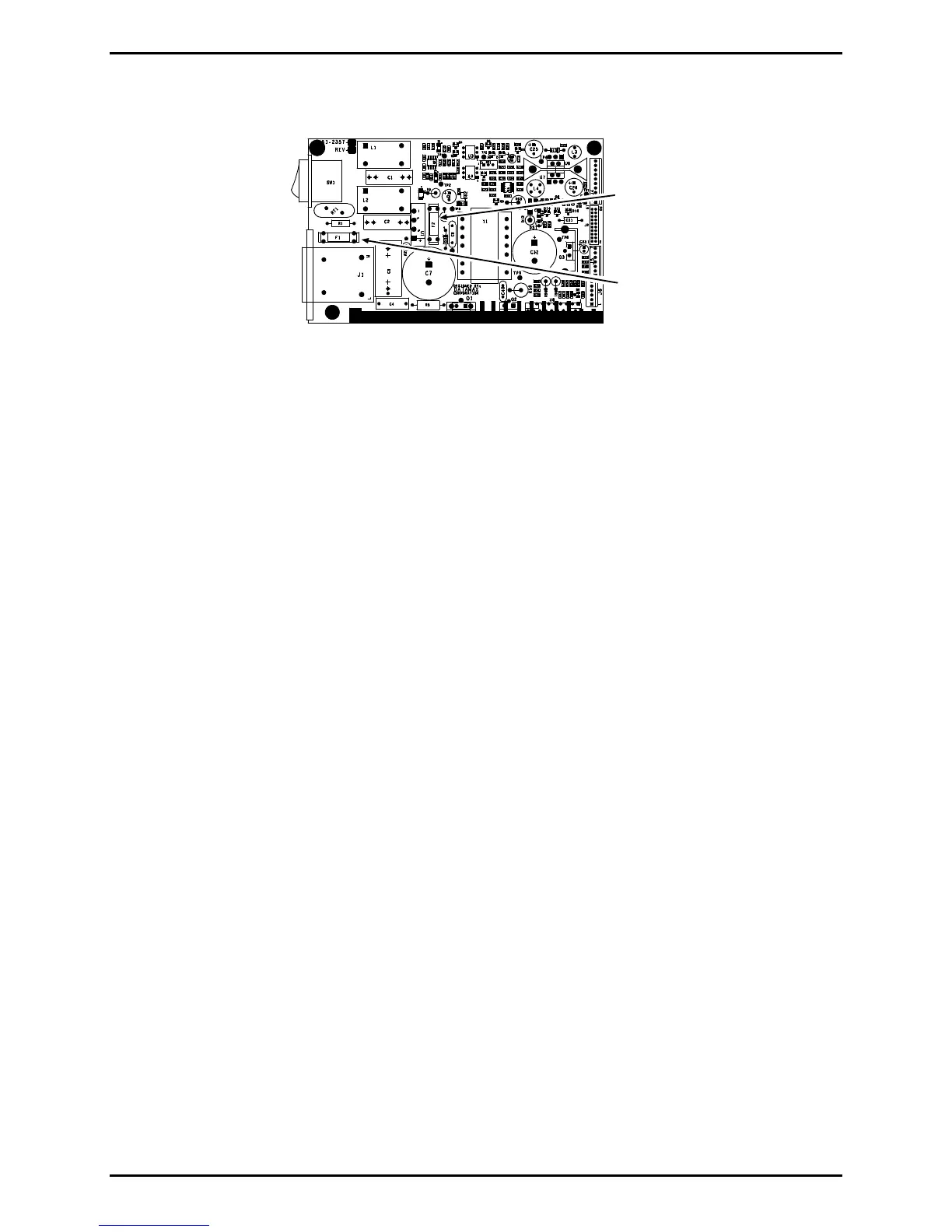
Fuse F1
Fuse F2
Power Supply PCB
Installation:
1. Only replace the defective fuse(s) with the same type and rating as the factory original:
• Fuse F1: Medium acting, 3 amps @ 250 Volts, 5 x 20 mm; and,
• Fuse F2: Fast acting, 3 amps @ 250 Volts, 5 x 20 mm.
2. Install the Side Cover Assembly; see Section 4.1.
4.6 Media Sensor
Removal:
1. Turn OFF and unplug the printer.
2. Remove the Side Cover Assembly; see Section 4.1.
3. Open the J7 Strain Relief on the Main Logic PCB then remove the Media Sensor Cable.
4. Unlatch the printhead assembly then remove the Screw and the Outer Bearing Plate.
5. Slide the Media Sensor & Cable Assembly out of the printer.

 Loading...