Removal and Replacement
4-19
2. Secure the Drive Motor to the Isolator using the two Lock Washers and Screws.
3. Connect the Drive Motor Cable to the J6 of the Power Supply PCB; see Section 4.5.
4. Proceed according to equipped type: If equipped with an Assist Roller, replace the Inner
Bearing Plate and secure it to the Platen Block using the Screw; otherwise, go to Step 6.
5. If removed, install the tearplate and fascia or other previously attached output device.
6. Install the Front Cover (see Section 4.2) and Side Cover Assembly (see Section 4.1).
4.7.1 Isolator
Removal:
1. Turn OFF and unplug the printer.
2. Remove the Drive Motor; see Section 4.7.
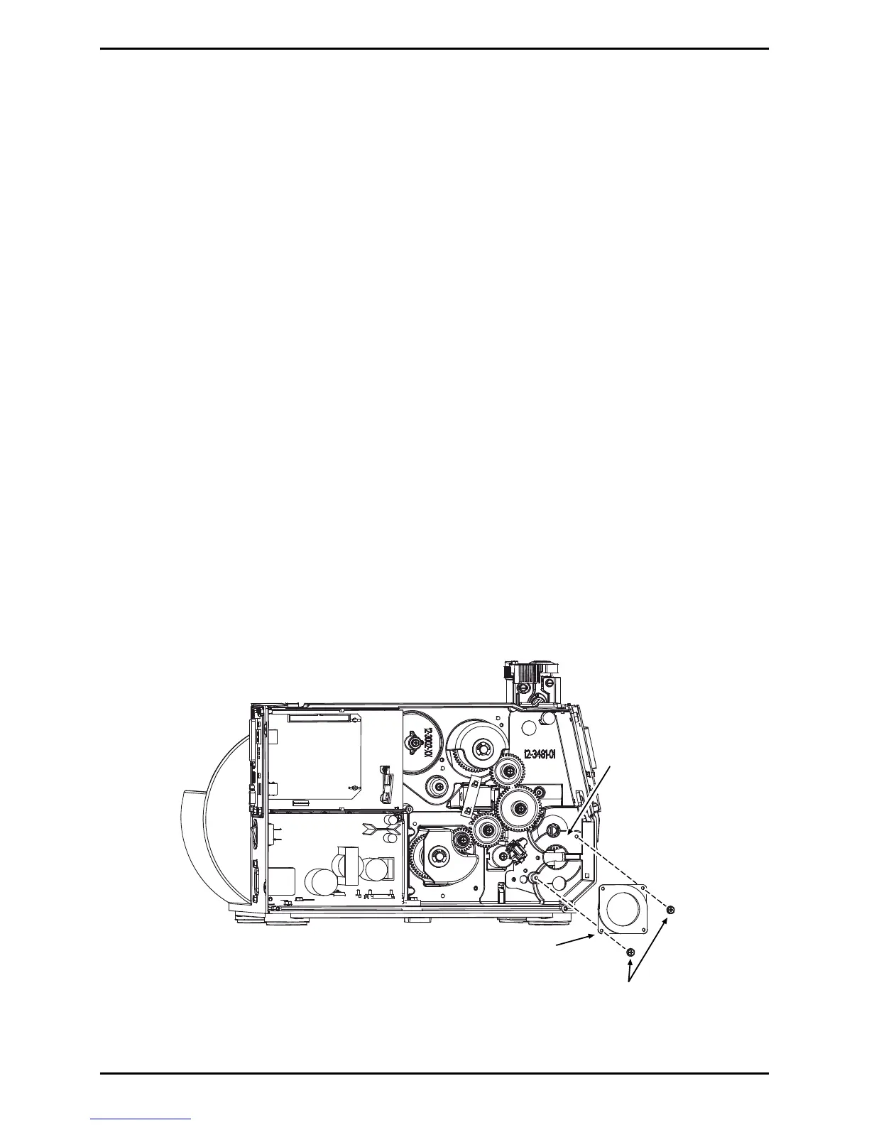
3. Remove the two Screws that secure the Isolator to the Centerplate then remove the
Isolator.
Screws
Isolator
Centerplate

 Loading...