Removal and Replacement
4-11
2. Place the Bottom Carriage into the Top Carriage, sliding it forward until the Catches
engage, and then tighten the Locking Screws.
3. Snug, but do not tighten, the Adjustment Screws.
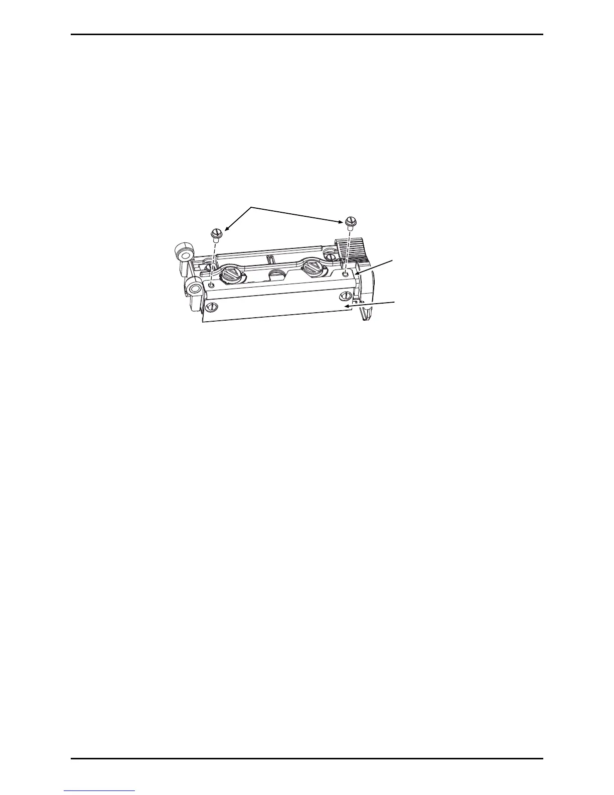
4. Install the Ribbon Shield onto the Top Carriage and secure it using the two Screws.
Ribbon
Shield
Top
Carriage
Screws
5. Install the Printhead Assembly; see Section 4.3.1.
6. Align the Printhead; see Section 2.4.
7. Adjust the Printhead Pressure; see Section 2.5.
8. If Thermal Transfer equipped, align the Ribbon Path; see Section 2.6.
4.4 Main Logic PCB
Removal:
1. Turn OFF and unplug the printer.
2. Remove the Side Cover Assembly; see Section 4.1.
3. Remove all cables connected to the Main Logic PCB.

 Loading...