EasyManuals Logo

Datamax M-Class Mark II Maintenance Manual

Datamax M-Class Mark II
94 pages
To Next Page IconTo Next Page
To Previous Page IconTo Previous Page
Page #76 background imageLoading...
Page #76 background image
Removal and Replacement
4-12
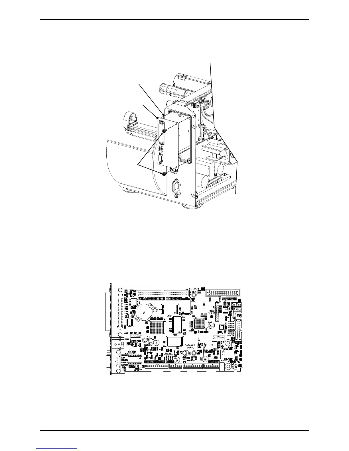
4. Remove the two Screws on the PCB Back Plate of the Main Logic PCB then slide out the
Main Logic PCB.
Screws
Main
Logic PCB
PCB Back
Plate
Installation:
1. Position the Main Logic PCB in the printer. Using the two Screws, secure the PCB Back
Plate to the printer.
2. Connect the cables to the Main Logic PCB.
J11
J14
J9
J10
J8
J6
J5
J4J16
J12
J7
Main Logic PCB
3. Install the Side Cover Assembly; see Section 4.1.
4. Calibrate the Media Sensor; see Section 2.2.

Table of Contents

Other manuals for Datamax M-Class Mark II

Questions and Answers:

Question and Answer IconNeed help?

Do you have a question about the Datamax M-Class Mark II and is the answer not in the manual?

Datamax M-Class Mark II Specifications

General IconGeneral
Media SensorAdjustable reflective and transmissive sensors
Print MethodThermal Transfer
Print Resolution203 dpi
Memory8 MB Flash, 16 MB SDRAM
Interface OptionsUSB, Serial, Ethernet, Parallel
Media TypeRoll-fed, die-cut, continuous, fan-fold, tags, ticket stock
Media Width1.0 in (25.4 mm) to 4.65 in (118 mm)
Media Thickness0.0025 in (0.0635 mm) to 0.010 in (0.254 mm)
Media Roll Diameter8 inches (203 mm) max
Ribbon Width1 to 4.33 inches (25.4 to 110 mm)
Ribbon Length1968 ft (600 m)
Ribbon Core1 inch (25.4 mm)
Label Width Range1.0 in (25.4 mm) to 4.65 in (118 mm)
Label Length Range0.25 to 39 inches (6.35 to 991 mm)

Related product manuals