Removal and Replacement
4-14
2. Secure the Ground Wire using the Screw and Lock Washer to the chassis.
3. Position the AC Input Retainer onto the AC Input Connector then secure it using the two
Screws.
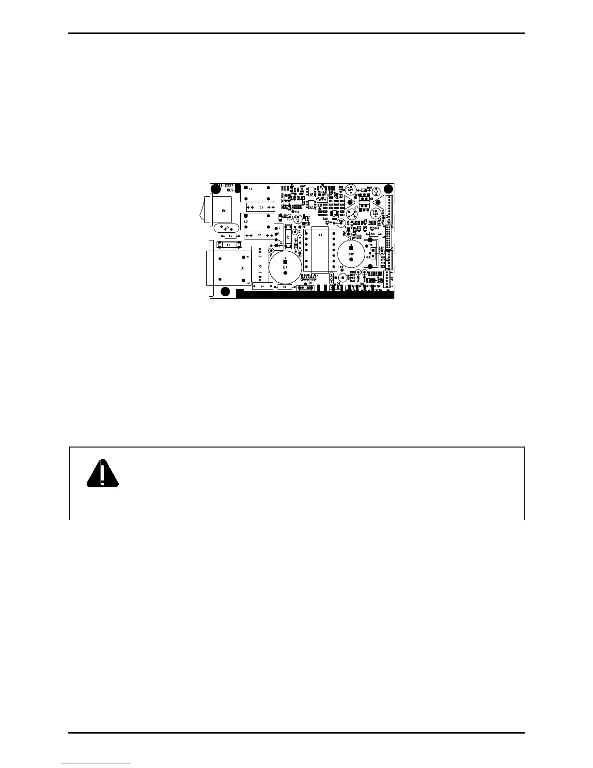
4. Connect the cables to the Power Supply PCB.
J4
J2
J5
J6
Power Supply PCB
5. Adjust the Printhead Voltage; see Section 2.10.
6. Install the Side Cover Assembly; see Section 4.1.
4.5.1 Fuses
CAUTION
Only use replacement fuses of the same type and rating as the originals;
failure to comply could cause serious damage, including fire; and,
Use care if replacing Fuse F1, which may blow during a failure in the
primary switching circuit and indicate a more serious electrical problem.
Removal:
1. Turn OFF and unplug the printer.
2. Remove the Side Cover Assembly; see Section 4.1.
3. Locate and test Fuses F1 and F2 on the Power Supply PCB.

 Loading...