6
Section 1
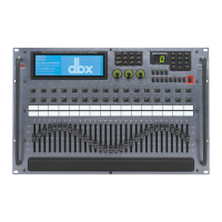
DriveRack
™
This LED (when lit), indicates that the 481 is connected to the control bus.
When it is flashing, the 481 is sending/receiving network information.
Remote LED
This LED (when lit), indicates that the 481 is connected to the 480R. When
it is flashing, the 481 is sending/receiving information from the 480R.
PC LED
This LED (when lit), indicates that the 481 is connected to the PC. When
it is flashing, the 481 is sending/receiving information from the PC.
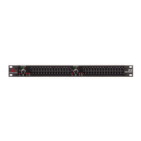
Input Meters
The 481 DriveRack™ provides the user with four independent 6-segment
lightpipe™ input meters that range from -30 to +22 dBu. Note: These
meters are calibrated for the +22dBu setting of the gain jumpers.
Output Meters
The 481 DriveRack™ provides the user with eight independent 6-segment
lightpipe™ output meters that range from -30 to +22 dBu. Note: These
meters are calibrated for the +22dBu setting of the gain jumpers.
Power Switch
Turns the 481 DriveRack™ on and off. Note: dbx Professional Products rec-
ommends that power amps connected to the DriveRack™ should be pow-
ered down prior to cycling the DriveRack™.
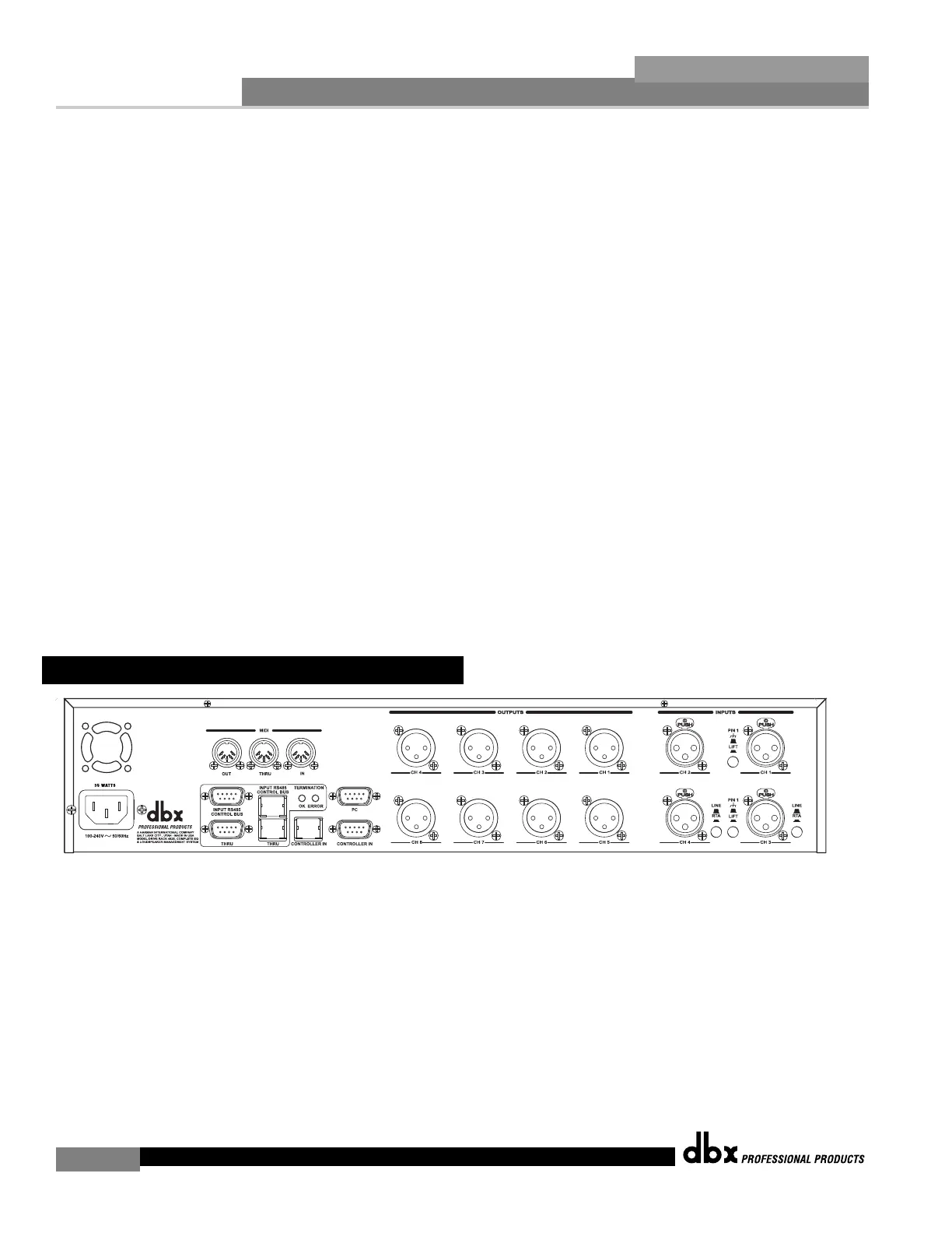
IEC Power Cord Receptacle
The 482 comes with an International power supply that will accept voltages ranging from 100V-240V
at frequencies from 50Hz-60Hz. An IEC cord is included.
MIDI In, Out and Thru Connectors
These connectors provide MIDI functionality to the 482 DriveRack™. The In, Out and Thru jacks
allow you to use the 482 DriveRack™ at any point in the MIDI chain.
RS485 Control Bus Input (DB-9 connector type)
This input network connection is used to receive information being sent from other units in the
DriveRack™ network link.
1.5 Rear Panel Connections (482)