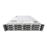
DM5500 rear view
3
2
10
1
89101112
1315 14
2 3 4 5 7
6
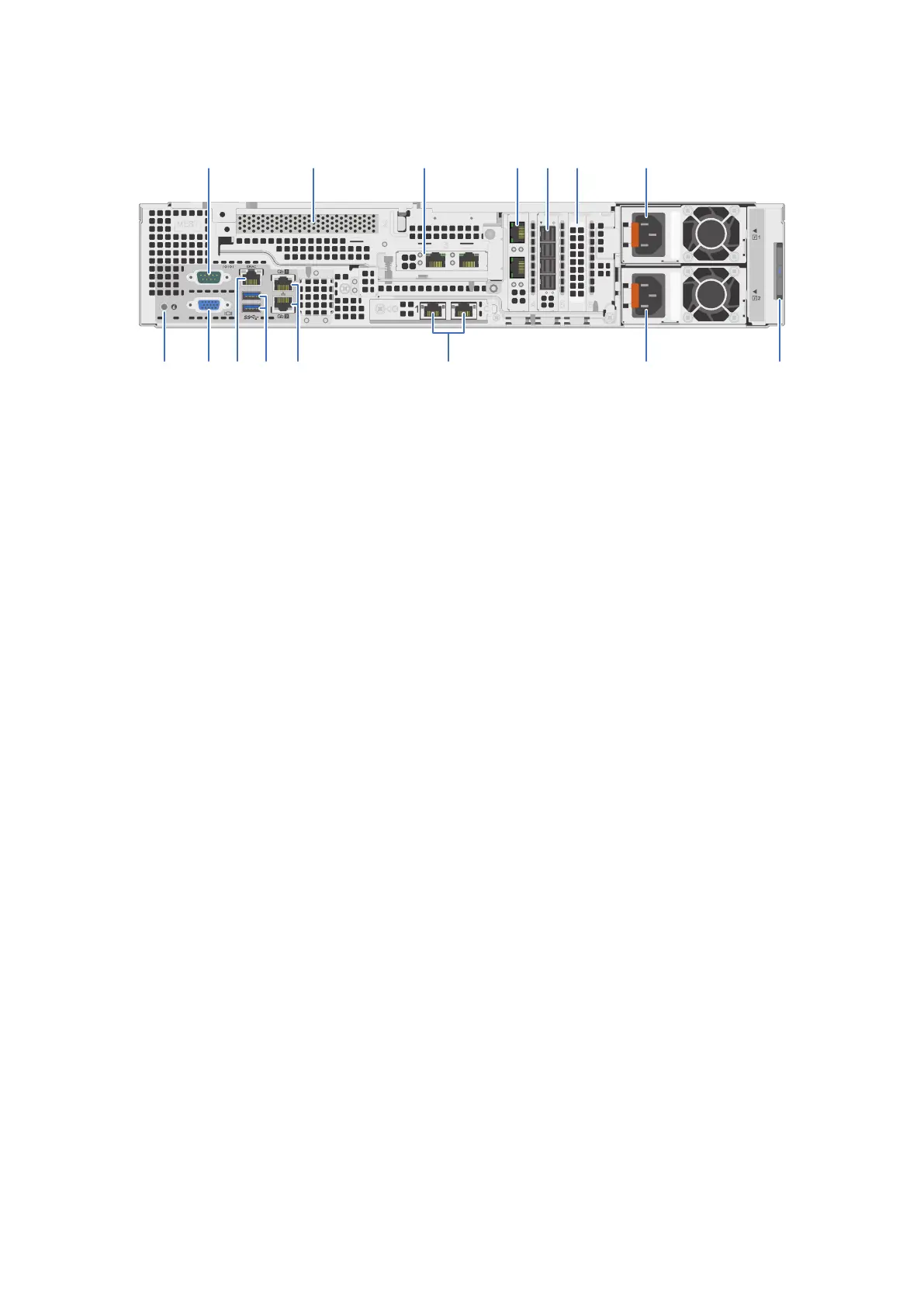
Figure 6. DM5500 back panel features
1. Serial port 2. Intel QuickAssist Technology (QAT) card (PCIe slot 2)
3. Dual or quad port expansion card (PCIe slot 3)
Can be configured to run as two 25 GbE SFP28 ports, two
10 GbE SFP+ ports, or four 10GBASE-T ports
4. Dual or quad port expansion card (PCIe slot 4)
Can be configured to run as two 25 GbE SFP28 ports, two
10 GbE SFP+ ports, or four 10GBASE-T ports
5. SAS HBA (PCIe slot 5) 6. Filler (unused) PCIe expansion card (PCIe slot 6)
7. Power supply unit (PSU 1)
PSU 1 can be 1100W or 1600W, but must be the same
wattage as PSU 2.
8. Information tag - this contains the DM5500 serial number.
The pull-out information tag contains a white label with the
14-character DM5500 serial number. The DM5500 serial
number is used as part of the default password when
you log in to the
PowerProtect Data Manager Appliance
Configuration UI for the first time when you perform the
initial
DM5500 configuration.
9. Power supply unit (PSU 2)
PSU 2 can be 1100W or 1600W, but must be the same
wattage as PSU 1.
10. LAN on motherboard (LOM) ethernet port (2) (PCIe slot 1)
Can be configured to run as two 25 GbE SFP28 ports, two
10 GbE SFP+ ports, or two 10GBASE-T ports
11. Ethernet port (2)
Gb1 and Gb2 service ports used for initial DM5500 login.
Only one of these ports at a time can be used for the initial
DM5500 login.
12. USB 3.0 port (2)
13. iDRAC9 dedicated network port 14. VGA port
15. System identification button
Expansion enclosure overview
This section describes the enclosure front and rear views, the LEDs, and how to locate the service tag.
Expansion enclosure front view
The front of the enclosure contains an LED panel and provides access to the service tag. Removing the front bezel provides
access to the enclosure drives.
● The enclosure supports twelve 8 TB 3.5 in. drives, mounted horizontally in the chassis.
Understand the PowerProtect Data Manager Appliance
17