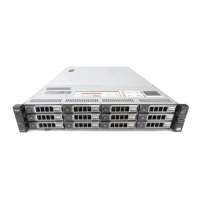
1 DM5500 front view..................................................................................................................................................14
2 Left control panel..................................................................................................................................................... 14
3 Right control panel...................................................................................................................................................15
4 Drive indicators......................................................................................................................................................... 15
5 View of drive bays extended................................................................................................................................. 16
6 DM5500 back panel features................................................................................................................................ 17
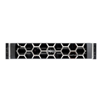
7 Expansion enclosure front view............................................................................................................................ 18
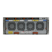
8 Expansion enclosure rear view.............................................................................................................................. 18
9 Front panel LEDs...................................................................................................................................................... 19
10 Drive carrier LEDs....................................................................................................................................................20
11 EMM LEDs.................................................................................................................................................................20
12 PSU LEDs................................................................................................................................................................... 21
13 24 TB usable capacity DM5500 drive configuration.......................................................................................22
14 96 TB usable capacity DM5500 drive configuration.......................................................................................23
15 L-Bracket Static rail................................................................................................................................................ 26
16 Installing the rail....................................................................................................................................................... 27
17 Correctly installed rear rack rail........................................................................................................................... 28
18 Chassis retention bracket on rear rack flange..................................................................................................28
19 Diagram and description of installing the chassis retention bracket...........................................................29
20 Correctly installed chassis bracket on rack flange.......................................................................................... 30
21 Remove the shipping screws................................................................................................................................ 30
22 Removing a drive carrier.........................................................................................................................................31
23 Removing a drive blank.......................................................................................................................................... 32
24 Removing the front bezel...................................................................................................................................... 33
25 Opening the drive bays...........................................................................................................................................34
26 Closing drive bays.................................................................................................................................................... 34
27 Removing a power supply unit..............................................................................................................................35
28 Diagram and description of installing the DM5500 into the rack................................................................ 36
29 Installing a drive....................................................................................................................................................... 38
30 Installing a drive blank.............................................................................................................................................38
31 Installing a power supply unit................................................................................................................................39
32 Installing the front bezel........................................................................................................................................ 40
33 DM5500 recommended network connections (optical SFP28/SFP+ ports)........................................... 42
34 DM5500 recommended network connections (copper 10GBASE-T ports)..............................................42
35 Connecting the rail to the back post.................................................................................................................. 45
36 Attaching the rail to the front post..................................................................................................................... 46
37 Securing the rails to the rack................................................................................................................................46
38 Installing the enclosure into the rack.................................................................................................................. 47
39 Securing the enclosure to the rack..................................................................................................................... 48
40 Installing the front bezel........................................................................................................................................ 48
Figures
Figures 5