1-14
Dell OptiPlex Gn and Gn+ Systems Service Manual
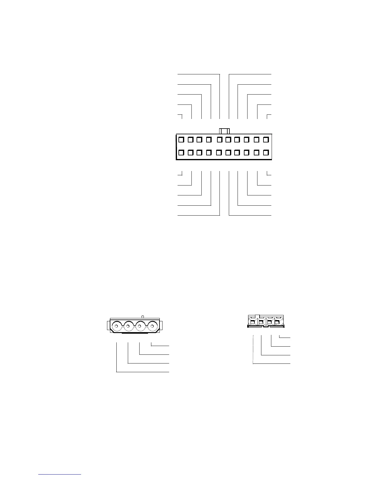
Pin Assignments for the DC Power Connectors
The power-supply output voltages can be measured at the back (wire side) of
the connectors without disconnecting them. Figures 1-10 through 1-12 show the
wire side of the connectors.
1
Pin 11 — PSON# should measure between +4 and +5 VDC except when the power button
on the front panel is pressed, taking PSON# to its active-low state.
2
Pin 19 — Thermal fan-speed control (TFSC) is a power-supply input signal used to control
the power-supply fan speed.
3
Pin 5 — PWRGOOD should measure between +4 and +5 VDC when the power supply is
operating to indicate that all power-supply output voltages are within the ranges specified
in Table 1-1.
Figure 1-13. DC Power Connector P1
Figure 1-14. DC Power Connectors P2 (Midsize and Mini Tower),
P3, P4, P5, P6, and P9
2 3 4 5 6 7 8 9 10
12 13 14 15 16 17 18 19 20
–5 VDC (white)
TFSC
2
(brown)