1-20
Dell OptiPlex Gn and Gn+ Systems Service Manual
System Board
The subsections that follow provide service-related information about the sys-
tem board and components. The same system board is used in the low-profile,
midsize, and mini tower computers.
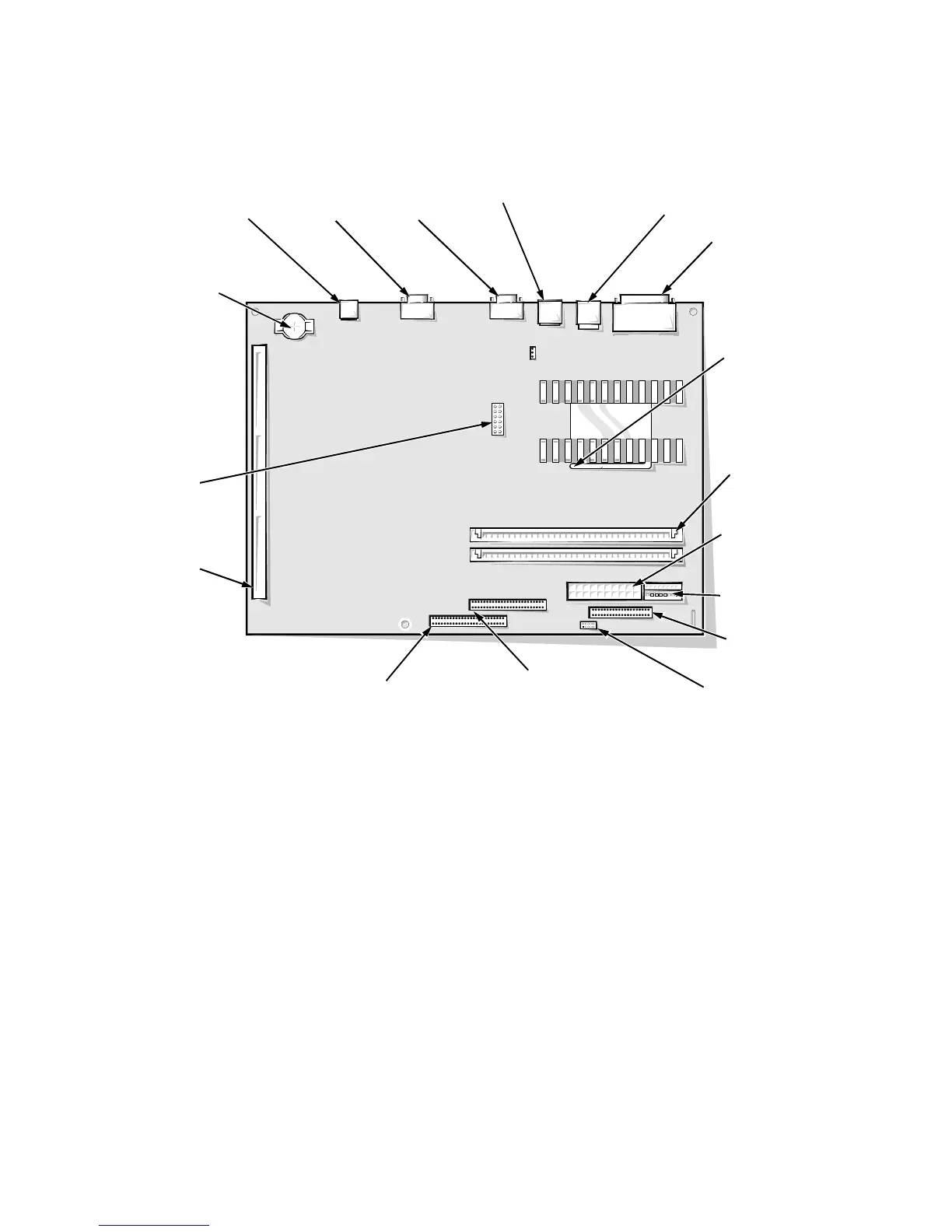
Figure 1-21. System Board Components
primary EIDE
interface connector
(IDE1) (pin-1 corner)
video connector
(MONITOR)
diskette/tape drive
interface connector
(DSKT) (pin-1 corner)
riser board
connector
(RISER)
serial port 2
connector
(SERIAL2)
system
board
jumpers
NIC connector
(ENET) (Gn+ only)
control panel
connector (PANEL)
3.3-V power input
connector (POWER2)
keyboard/mouse
connectors (stacked)
(KYBD/MOUSE)
main power input
connector (POWER1)
microprocessor socket
(MICROPROCESSOR)
(pin-1 corner)
DIMM sockets (2)
(DIMM_A)
USB connectors
(USB)
parallel/serial port 1
connectors (stacked)
(PARALLEL/SERIAL 1)
battery socket
(BATTERY)
secondary EIDE
interface connector
(IDE2) (pin-1 corner)