Hardware Description 63
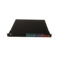
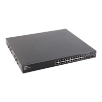
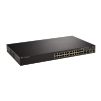
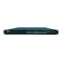
Figure 4-13. Connecting a Stack of PowerConnect 6200 Series Switches
In Figure 4-13, the stack has the following physical connections between the switches:
• Unit 1 and Unit 2 are connected through the XG1 ports on each switch.
• Unit 2 and Unit 3 are connected through the XG2 ports on each switch.
• Unit 1 and Unit 4 are connected through the XG2 port on Unit 1 and the XG1 port on Unit 4.
The resulting ring topology allows the entire stack to function as a single switch with
resilient fail-over
capabilities.
Stacking Standby
The stacking feature supports a “Standby” or backup unit that will assume the Master unit role if the
Master unit in the stack fails. As soon as a Master failure is detected in the stack, the Standby unit
initializes the control plane and enables all other stack units with the current configuration. The Standby
unit maintains a synchronized copy of the running configuration for the stack.
The Standby unit is preconfigured in the stack; however, you can use the CLI to select a different stack
member as Standby. See the CLI Reference Guide for more information.
Unit 1
Unit 2
Unit 3
Unit 4
XG1 Port XG2 Port
 Loading...


