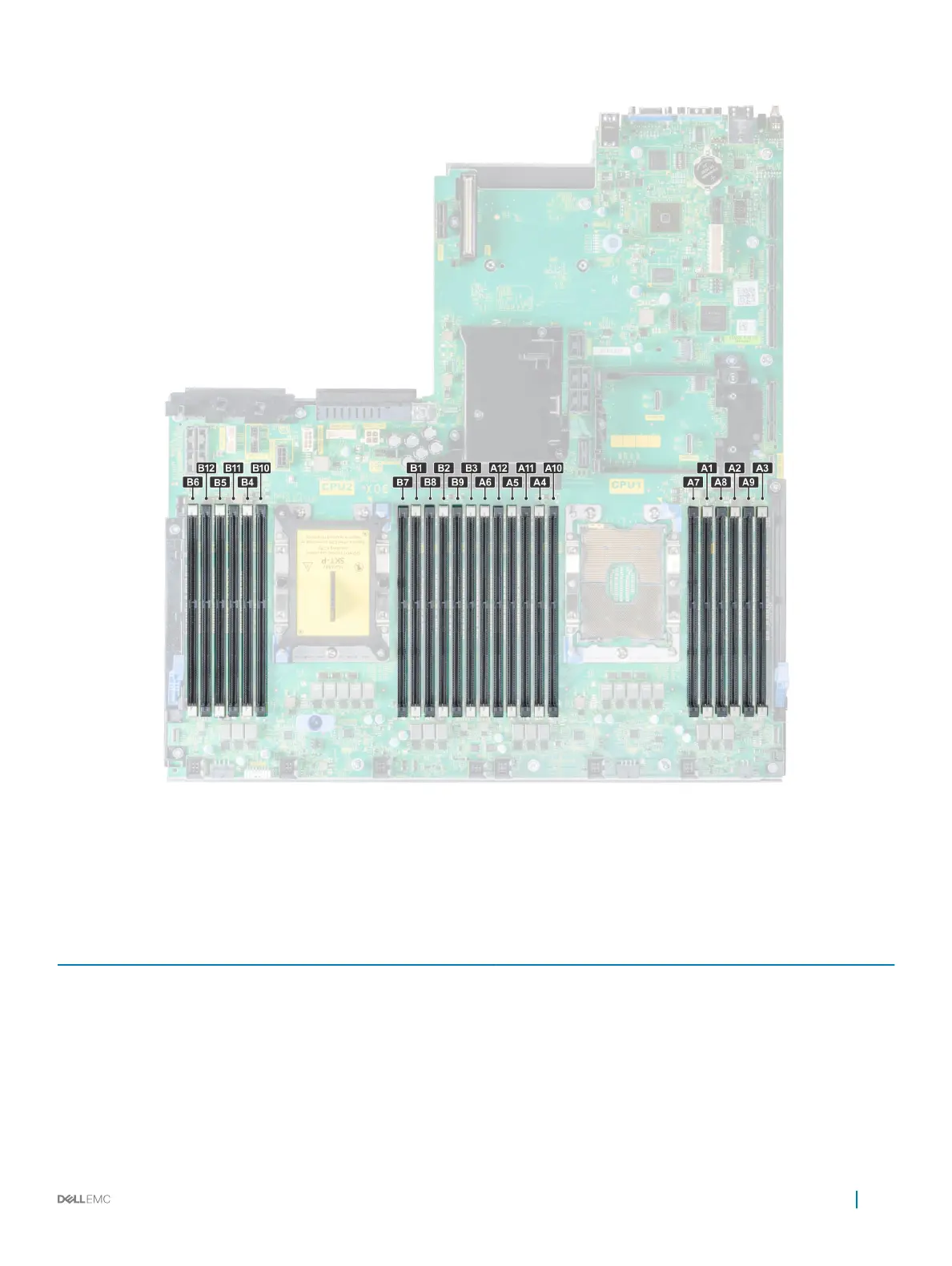
Figure 61. Memory socket locations
Memory channels are organized as follows:
Table 39. Memory channels
Proces
sor
Channel 0 Channel 1 Channel 2 Channel 3 Channel 4 Channel 5
Proces
sor 1
Slots A1 and A7 Slots A2 and A8 Slots A3 and A9 Slots A4 and A10 Slots A5 and A11 Slots A6 and A12
Proces
sor 2
Slots B1 and B7 Slots B2 and B8 Slots B3 and B9 Slots B4 and B10 Slots B5 and B11 Slots B6 and B12
Installing and removing system components 111

 Loading...


