NOTE: Ensure that the PHM is held parallel to the system board to prevent damaging the components.
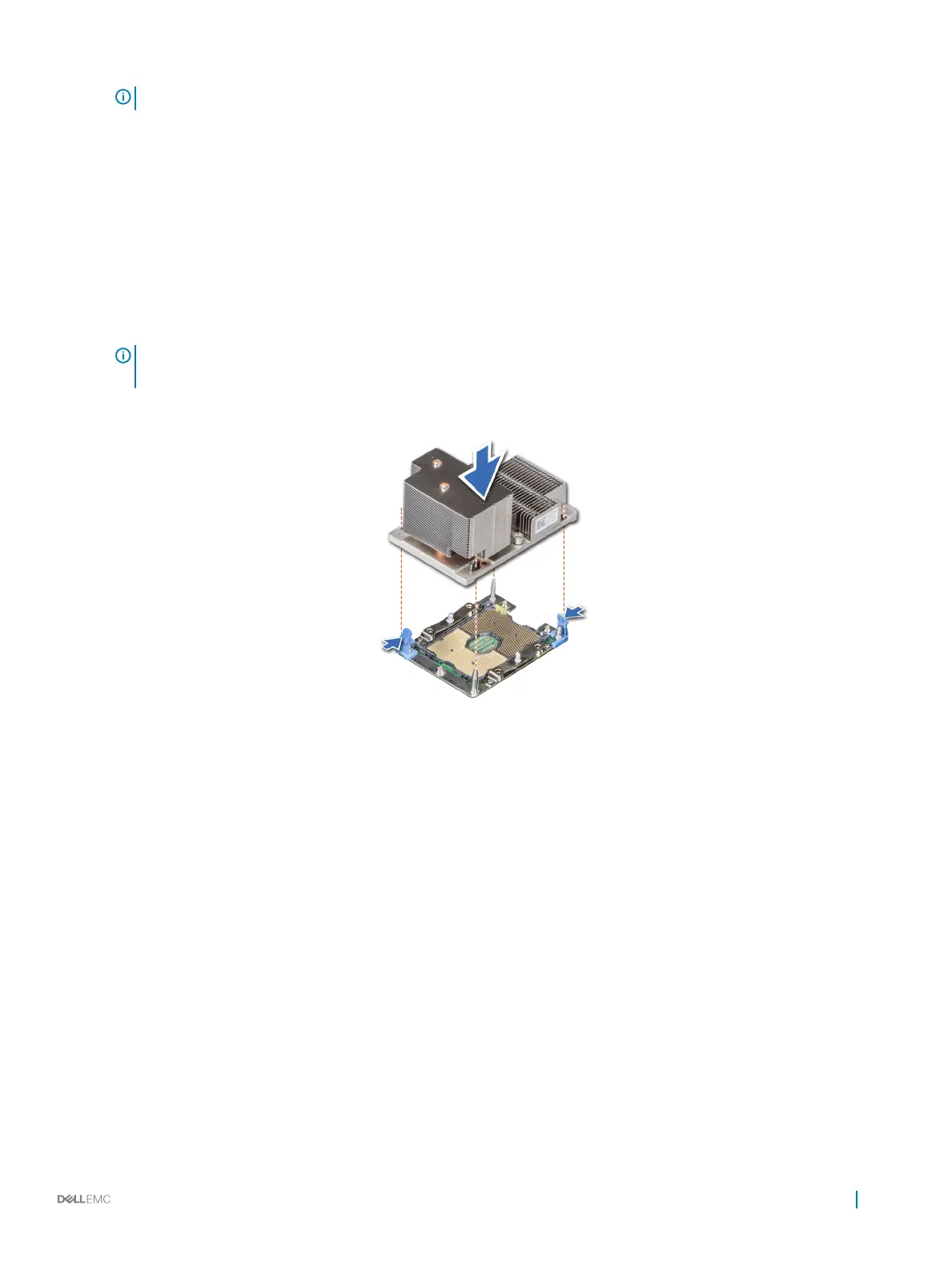
2 Push the blue retention clips inward to allow the heat sink to drop into place.
3 Supporting the heat sink with one hand.
4 Using the Torx #T30 screwdriver, tighten the screws on the heat sink in the order below:
a Partially tighten the rst screw (approximately 3 turns).
b Tighten the second screw completely.
c Return to the rst screw and tighten it completely.
If the PHM slips o the blue retention clips when the screws are partially tightened, follow these steps to secure the PHM:
a Loosen both the heat sink screws completely.
b Lower the PHM on to the blue retention clips, follow the procedure described in step 2.
c Secure the PHM to the system board, follow the procedure described in step 4.
NOTE: The processor and heat sink module retention screws should not be tightened to more than 0.13 kgf-m (1.35 N.m
or 12 in-lbf).
Figure 71. Installing the processor and heat sink module (2U)
Installing and removing system components
123

 Loading...


