3. EXTERIOR LOOK OF DCS CONTROLLER AND DESCRIPTIONS OF CONNECTORS
3.3.1
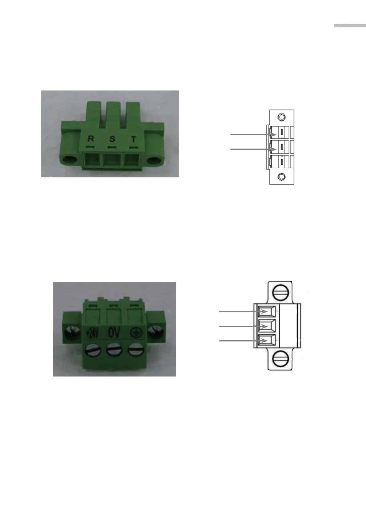
Definitions of pins on major loop power terminal:
The circuit input terminal of the main circuit; connect AC 200V to 230V single-phase 50/60 Hz
input power.
R
S
Figure 3-3 Actual main circuit circuit power
connector figure
Figure 3-4 Definition for the motor
power terminal
3.3.2
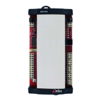
Definitions of pins on control power terminal:
Connect +24VDC (3A) input power to the control circuit input terminal.
Figure 3-5 Connector for power on
control circuit
DC 24V
24G
GND
Figure 3-6 Definition for the control
power terminal