SCARA ROBOT DCS ELECTRIC CONTROL INSTRUCTIONS
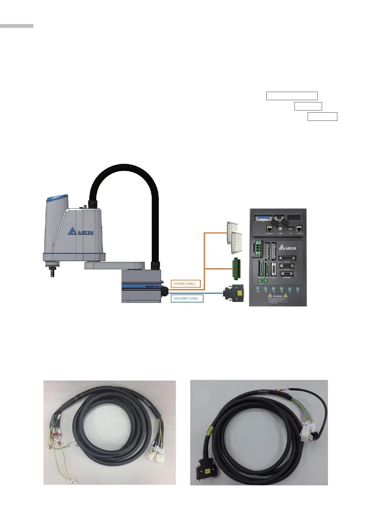
3.4 Wiring for ROBOT and controller:
Two cables must be connected between the controller and SCARA body:
1. Motor Power Cable: The outlet connectors from the base of SCARA are two sets of 6P male con-
nectors which are connected to the female ports for MOTOR POWER on the
controller; and J3 brake is connected to Pin 5 and Pin 6 on the BRK.DIO port,
the cable of button for unlocking J3 brake connect to Pin 1 on the
port.
2. Encoder Cable: The connector from the base of SCARA is MDR 26PIN connectors and con-
nects to MOTOR ENC on the controller.
Figure 3-7 Wiring diagram for the SCARA and MS controller
3.4.1 Specifications for connectors on the base and controller
1. Motor power cable: 0.75mm2 *20C (Shield) +
[DINKLE] 0134-34-06P*2
2. Encoder cable: 24AWG * 8 P + [3M] MDR 26PIN
Figure 3-8 Motor Power Cable Figure 3-9 Motor Encoder Cable