SCARA ROBOT DCS ELECTRIC CONTROL INSTRUCTIONS
3.4.3 Definitions for connectors for motor brake (BRK.DIO)
This function mainly provides DC24V to release the motor from its brake status. Through communi-
cation function, it utilizes DO function to give orders to output the signal for unlocking the brake. This
connector provides four sets of signals to unlock motor brake. Out of the four groups, one is for use
by SCARA J3 vertical axis and the other is for use by the button to release motor brake on J3 axis.
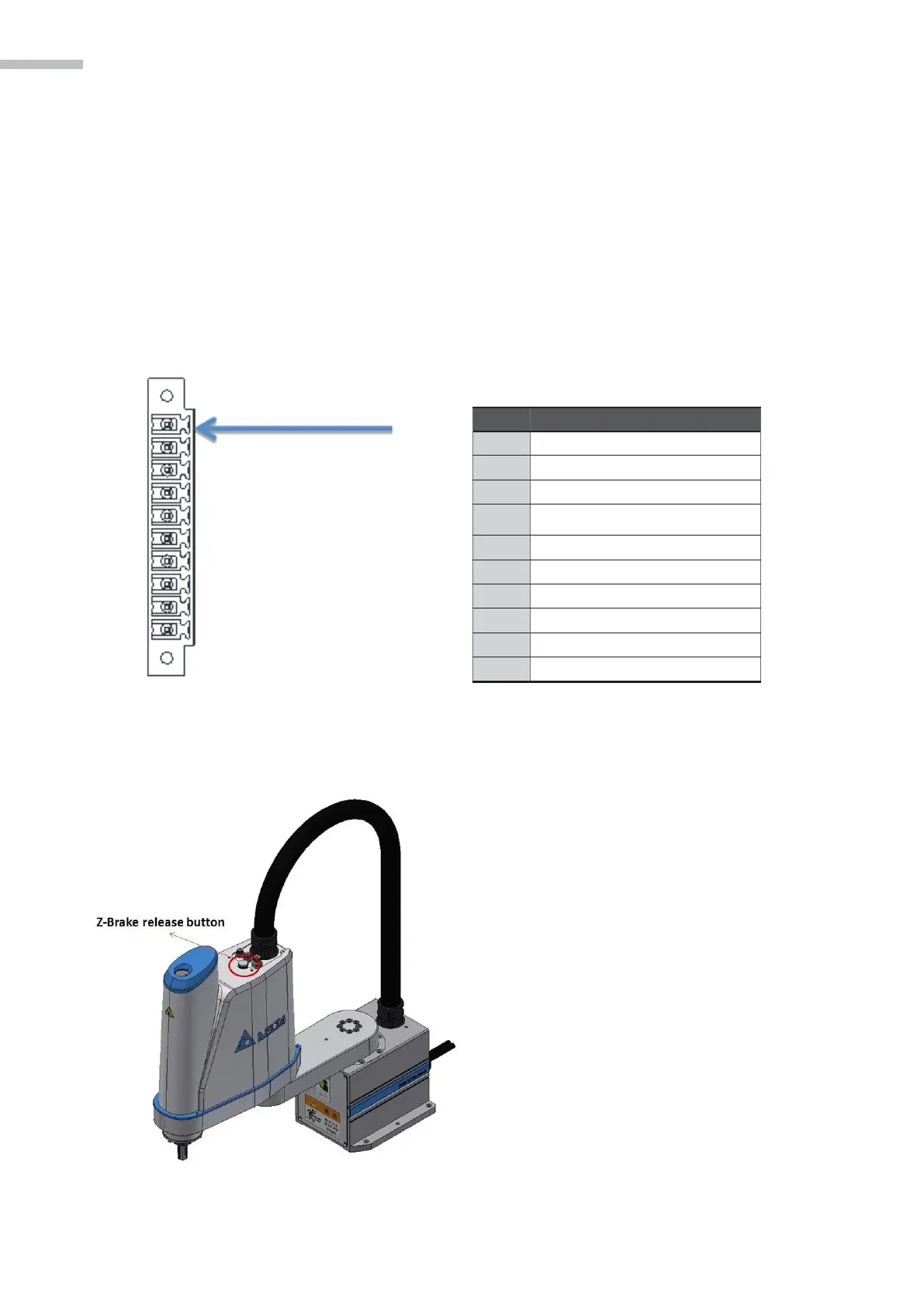
Figure 3-12 Definitions of pins for motor brake
Pin definition:
1.
J3 axis motor brake signal: ZBK and 24G are connected to Pin5 and Pin6.
2.
Signal for release of button on J3 axis motor brake: 24V is connected to Pin1
Table 3-3 Definitions of the motor pins
Figure 3-12 Definitions of Encoder pins
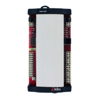
Figure 3-13 Brake Release Button Location
Brake release button function description:
This button is located on the head of SCARA, as
shown in the figure to the left; if the system servo
went off and caused the J3 axle brake to lock down,
pressing this button will release the J3 brake, allow-
ing users to manually move the J3 axle and perform
operations more conveniently.
Note: If load is added to the head, users must be-
ware that when this button is pressed, the unlocked
J3 axle break will slide downwards.
Note: if loads are added on the top, watch out for
fall down of J3 axis unlocking brake with this but-
ton pressed.