SCARA ROBOT DCS ELECTRIC CONTROL INSTRUCTIONS
3.4.5 STD.DIO connectors
The connector is defined based on pins used for input and output by the user’s IO. Currently, the in-
ternally planned I/O is described as follows and the other parts are available to users.
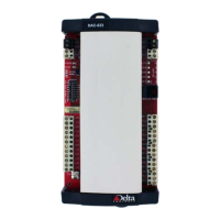
Figure 3-16 External View of the Connectors
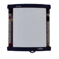
Figure 3-17 Configuration of Rear Pins
Table 3-6 Definitions of pins for user
’
s IO