SCARA ROBOT DCS ELECTRIC CONTROL INSTRUCTIONS
Table 3-7 Definitions of the pins for system IO Table 3-8 Definitions of functions for the system I/O
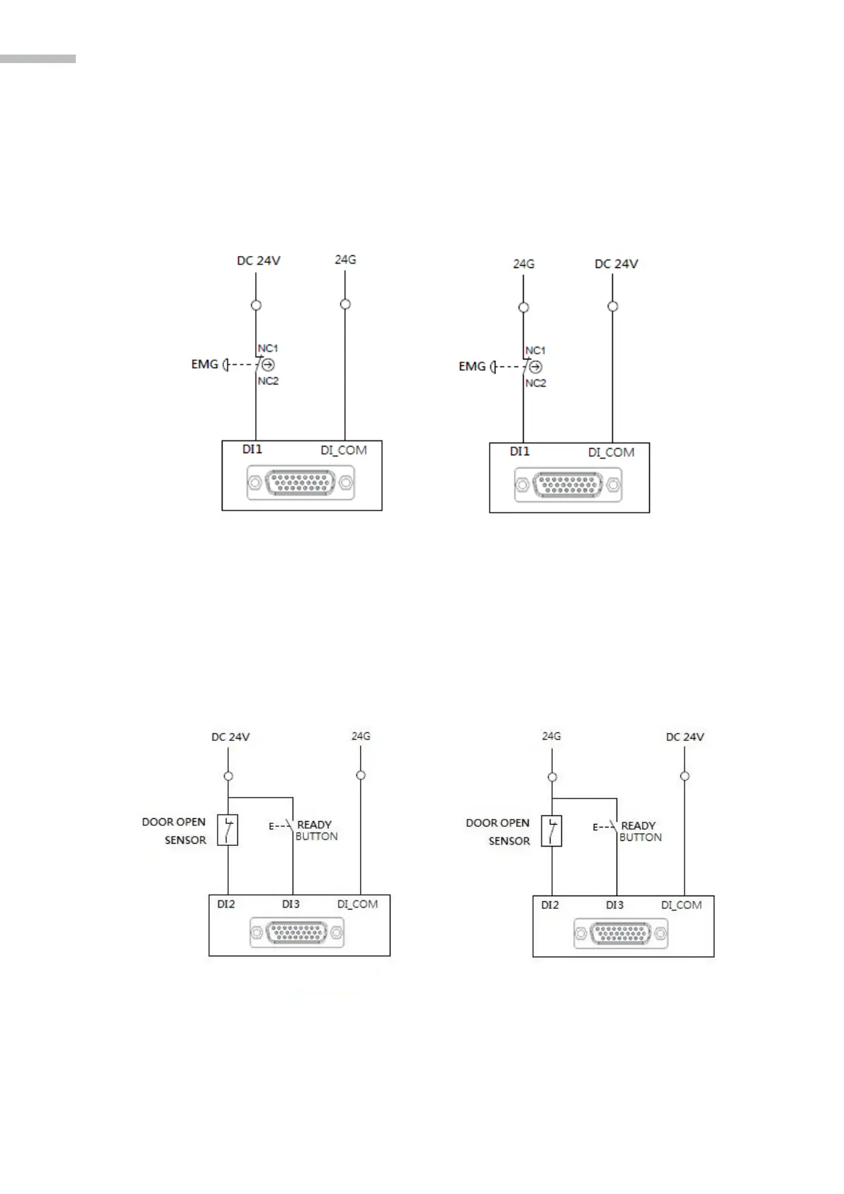
E-STOP signal:
E-STOP Input is the DI1 (Pin16) connected to SYS.DIO, therefore users must connect DI1 of this
connector to the external emergency stop button switch to use. E-STOP wiring example is as shown in
the figure.
Figure 3-19 E-STOP Wiring Example
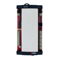
SAFETY DOOR Signal
There are two input points planned on the safety door; DI2 is the door opening detection sensor input
and DI3 is the door reversion ready button. As shown in the figure.
Figure 3-20 Wiring Example of the Safety Door