EasyManua.ls Logo

Delta DCS

Delta DCS
67 pages
To Next Page IconTo Next Page
To Previous Page IconTo Previous Page
Loading...
13
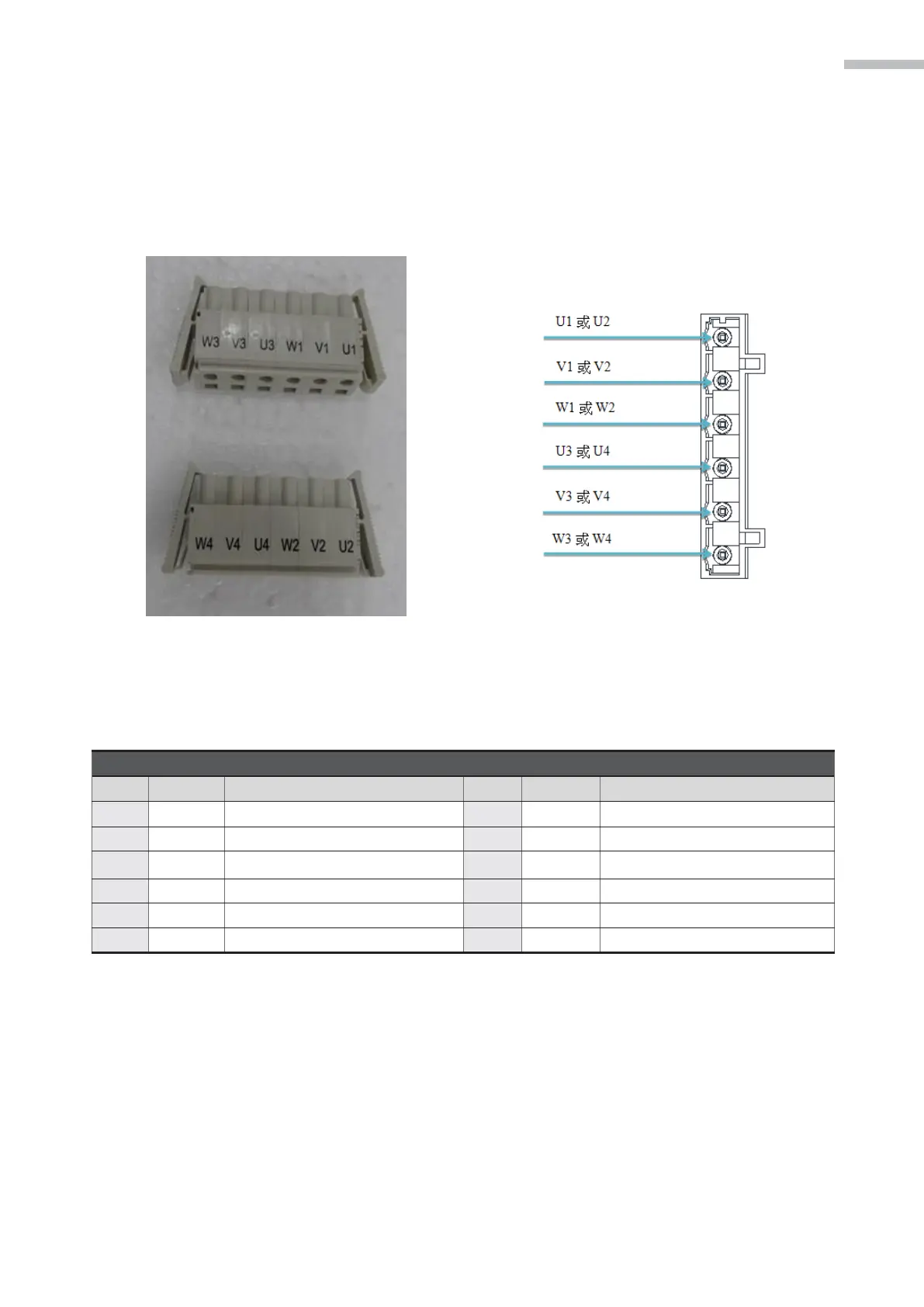
3. EXTERIOR LOOK OF DCS CONTROLLER AND DESCRIPTIONS OF CONNECTORS
3.4.2 Definitions for connectors on motor power cable
The connectors are connected to the motor power cable and shall be connected according to U, V
and W specifications. Part of the power cable use the same connectors J1+J3 and J2+J4 shared by
both axiss, so the marking shall be made when inserting the connectors.
Figure 3-10 Motor connectors Figure 3-11 Connectors on motor power cable
Table 3-2 Definitions for 4.2 in-flight connectors on motor power cable
Motor POWER connectors
Pin
Definition
Description
Pin
Definition
Description
1
U1
J1 motor power supply
1
U2
J2 motor power supply
2
V1
J1 motor power supply
2
V2
J2 motor power supply
3
W1
J1 motor power supply
3
W2
J2 motor power supply
4
U3
J3 motor power supply
4
U4
J4 motor power supply
5
V3
J3 motor power supply
5
V4
J4 motor power supply
6
W3
J3 motor power supply
6
W4
J4 motor power supply

Table of Contents

Related product manuals