SCARA ROBOT DCS ELECTRIC CONTROL INSTRUCTIONS
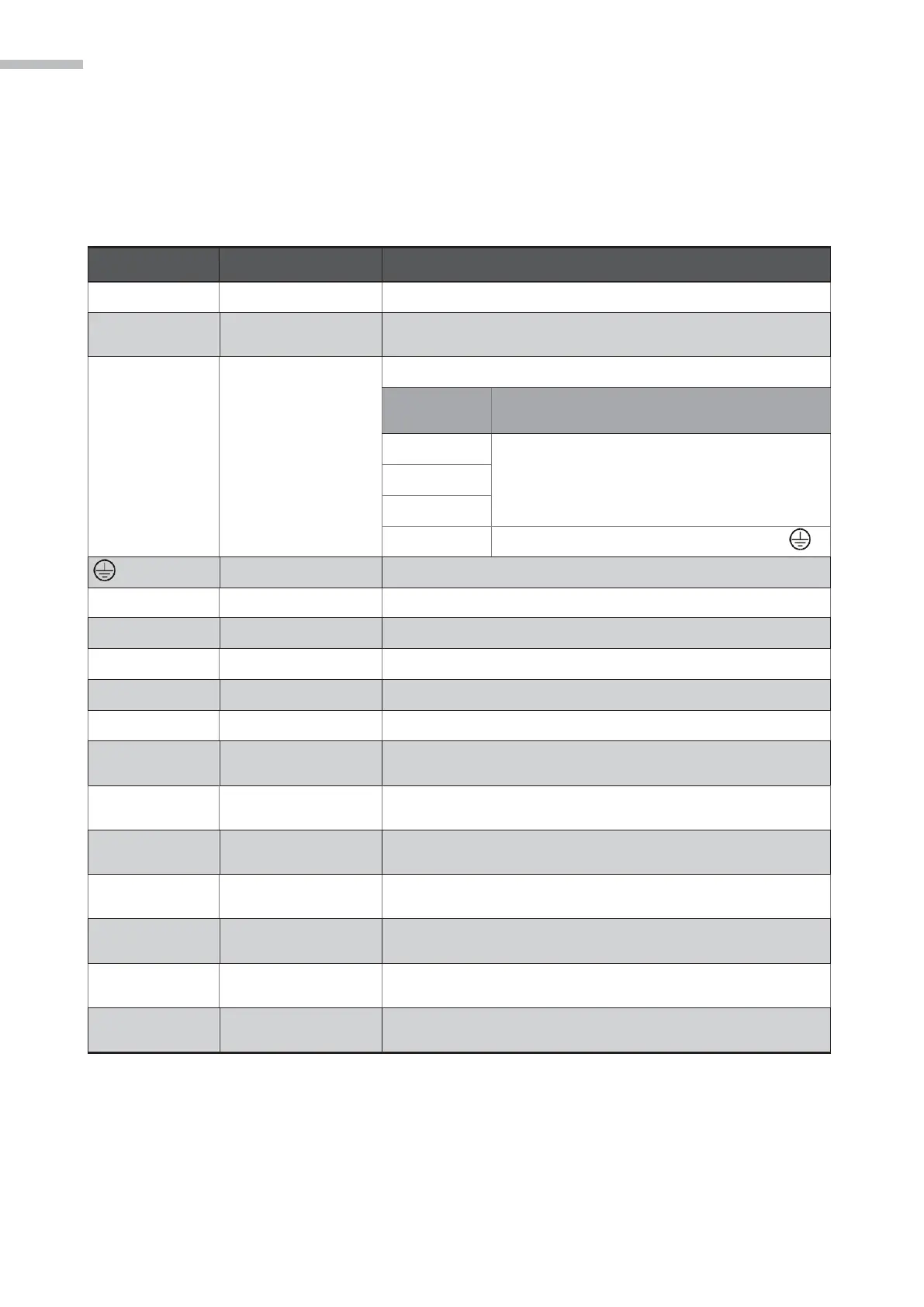
3.3 Definitions and descriptions for terminals on the
DCS controller
Table 3-1 Manual power pin
Connect 24V DC power supply
Power input end for
major loop
Connect single-phase AC power supply (220V AC)
U1, V1, W1
U2, V2, W2
U3, V3, W3
U4, V4, W4
FG
Connect to the motor power cable
Main power cable for the motor
Connect to grounding terminal of the drive
Connect with ground wires for the power supply and motor
Release electromagnetic brake on the motor
Communication port
connector
Connect RS-232 (supports Modbus ASCII Server)
Communication port
connector
Communication port
connector
Connect the internet (supports Modbus TCP/IP Server)
Communication port
connector
Communication port
connector
Communication port
connector
Connect related Delta products