3. EXTERIOR LOOK OF DCS CONTROLLER AND DESCRIPTIONS OF CONNECTORS
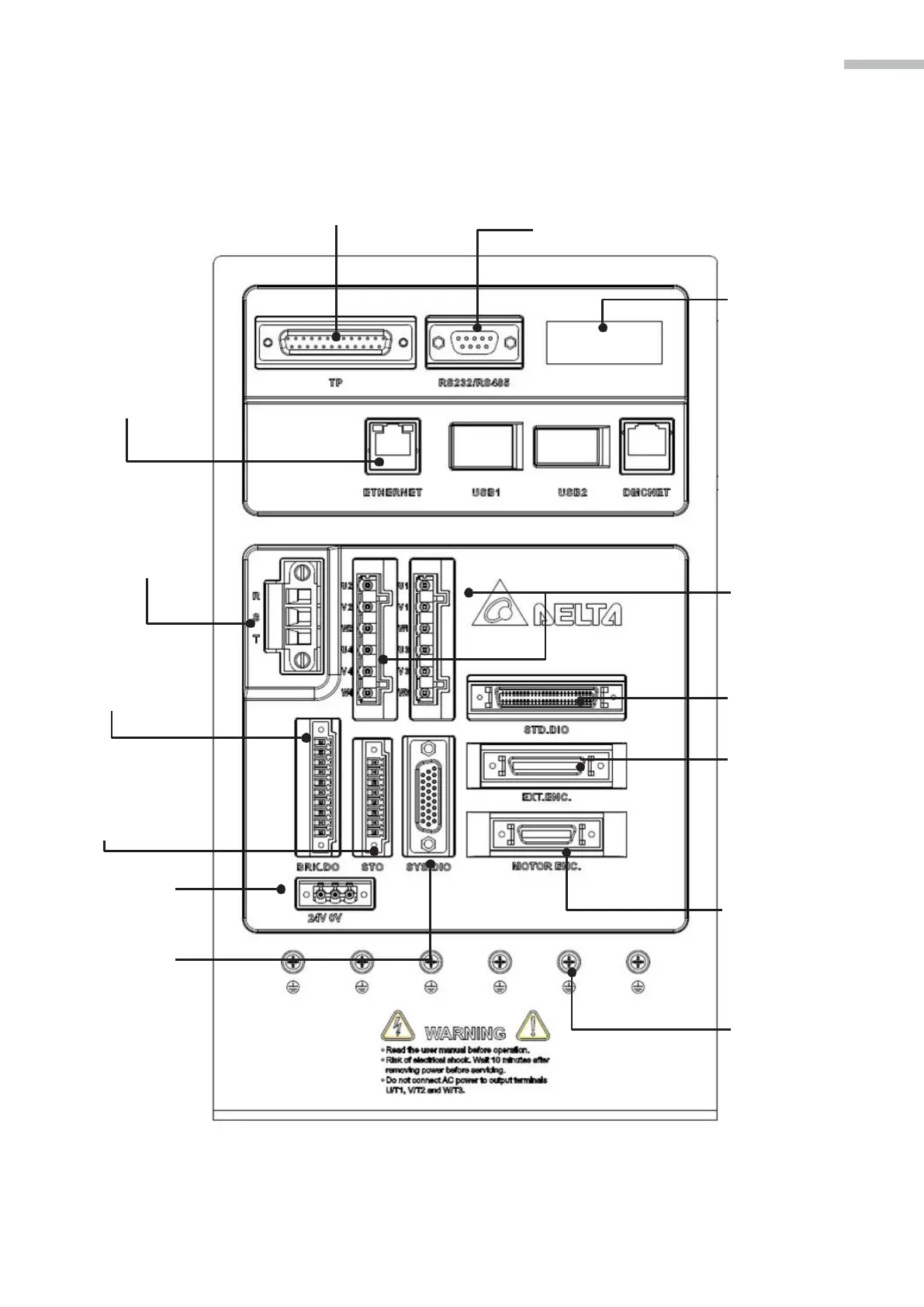
3.2 Descriptions of external ports on the DCS controller
Teaching Pendant Connection Port
Used to connect the teaching pendant
Serial Communication Port
For MODBUS communication control, sup-
porting RS-485 / RS-232 serial
communication.
High-speed Communiction Port
(Ethernet) / USB Connetion Port
(USB1, USB2) / DMCNET
Connection Port (DMCNET)
• Ethernet: Used to connect PCs
or ntebooks, capable of accesing
data through DROE software.
• USB1, USB2: Direct connectivity
to USB flash drives
• DMCNET: Used to connect
DMCNET peripherals
LED Display
The 5 digit, 7 segment
LED displays the controller status
or fault codes.
Main Circuit Terminal (R, S)
Used to connect 200 ~ 230Vac,
50/60Hz commercial power
supply.
Servo Motor Output (U, V, W)
Used to connect servo motor.
Never connect the output terminal
to main circuit power as the AC
drive may be damaged beyond
repair if incorrect
cables are connected
to the output terminals.
Motor Brake Output Terminal
(BRK. DIO)
Standard I/O Terminal
(STD. DIO)
STO I/O Terminal
(Safe Torque Off)
Used to connect a certified
safety relay or switch for
controlling STO I/O signals.
Control Circuit Terminal
Used to connect DC24V
power supply.
System I/O Terminal
(SYS. DIO)
Full-Closed Loop Control
Interface (EXT. ENG)
Used to connect linear scale
and encoder. Feeds back
the position signals of the full
closed linear scale and encoder
for controlling A, B, Z phase
signals.
Motor Encoder Interface
(MOTOR. ENC.)
Used to connect the encoder
signals of four servo motors
Ground Terminal
Used to connect grounding
wire of power supply and servo
motor.
Figure 3-2 Descriptions of external pins on the back of the controller