3. EXTERIOR LOOK OF DCS CONTROLLER AND DESCRIPTIONS OF CONNECTORS
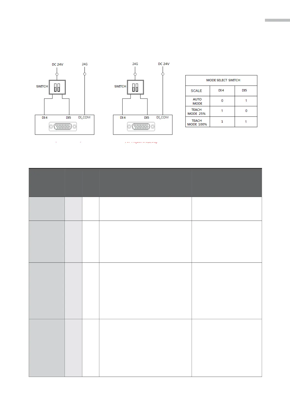
MODE SELECT Signal
The mode selection is planned via 2 input points, as shown in the figure below.
Figure 3-21 MODE SELECT Wiring Example
•
The controller LED displays E1.998
This mode will be deactivated
after the wire is connected
correctly.
•
The user must not use the teach
pendant to control the robot.
•
The user may use the PC to control
the robot.
•
The user may use the systematic
digital input to control the operation
The JOG synthetic speed shall
not exceed 250 mm/s (latch
JOG and shaft JOG)
•
The maximum running speed is less
than 250 mm/s.
•
The user may use the teach pendant
to control the robot.
•
The user may use the PC to control
the robot.
•
The user may not use the systematic
digital input to control the operation.
The JOG synthetic speed shall
not exceed 250 mm/s (latch
JOG and shaft JOG)
•
The maximum running speed is 2000
mm/s.
•
The user may use the teach pendant
to control the robot.
•
The user may use the PC to control
the robot.
•
The user may not use the systematic
digital input to control the operation.
The maximum running speed
is less than 250 mm/s.