VFD-L Series
DELTA ELECTRONICS, INC. ALL RIGHTS RESERVED
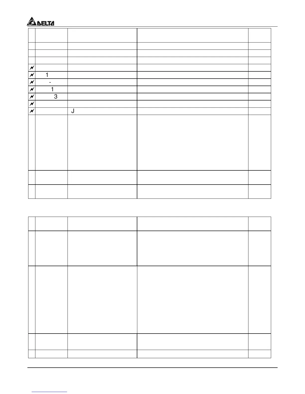
aramete
Functions Settings
Factor
Settin
1-06 Minimum output voltag
2.0 ~ 255V 12.0
1-07 Upper bound of freq. 1 ~ 110% 100
1-08 Lower bound of freq. 0 ~ 100% 0.0
=
1-09 Accel time 1 (Tacc1) 0.1 ~ 600 Sec 10.0
=
1-10 Decel time 1 (Tdec1) 0.1 ~ 600 Sec 10.0
=
1-11 Accel time 2 0.1 ~ 600 Sec 10.0
=
1-12 Decel time 2 0.1 ~ 600 Sec 10.0
=
1-13 JOG Accel time 0.1 ~ 600 Sec 10.0
=
1-14 JOG Decel time 0.0 ~ 600 Sec 10.0
=
1-15 JOG frequency 1.0Hz~400Hz 6.0
1-16 Auto-accel/decel
0: Linear Accel/Decel
1: Auto accel, linear decel
2: Linear accel, auto decel,
3: Auto Accel/Decel
4: Linear accel. Auto decel, stall
prevention during deceleration
5: Auto accel. Linear decel, stall
prevention during deceleration
0
1-17
S-curve setting in
acceleration
0 ~ 7 0
1-18
S-curve setting in
deceleration
0 ~ 7 0
Group 2: Operation Method Parameters
aramete
Functions Settings
Factor
Settin
2-00 Source of frequency
command
0: Digital keypad
1: 0 ~ 10V from AVI
2: 4 ~ 20mA from AVI
3: Controlled by V.R on drive
4: RS-485 communication interface
0
2-01 Source of operation
command
0: By digital keypad
1: By external terminals, keypad STOP
enable
2: By external terminals, keypad STOP
disable
3: By RS-485 communication interface,
keypad STOP enable
4: By RS-485 communication interface,
keypad STOP disable
0
2-02 Stop method
0: Ramp stop
1: Coast stop
0
2-03 Carrier freq.
3 ~10K Hz
10

 Loading...


