XT Series Programming Guide Digital Monitoring Products, Inc.
39
APPENDIX
Activate Cell (263C Only)
Note: (Version 122 or higher rmware) If the 263C Cellular Communicator has not been previously
activated, Automatic Cellular Activation is performed when the panel powers up or is reset. ACTIVATE
CELL is only necessary when Automatic Cellular Activation is not successful and communication was not
established.
To begin the cellular activation for a 263C CDMA Cellular Communicator, verify that the 263C MEID has
been added for the panel using Remote Link or by calling Customer Service (1-800-641-4282). At the
keypad, press any select key or area when ACTIVATE CELL is displayed on the keypad. When the
SURE NO YES? conrmation menu appears press the select key or area beneath YES to complete the
cellular activation.
Successful Display Failure Display
CELL ACTIVATED NOT ACTIVATED
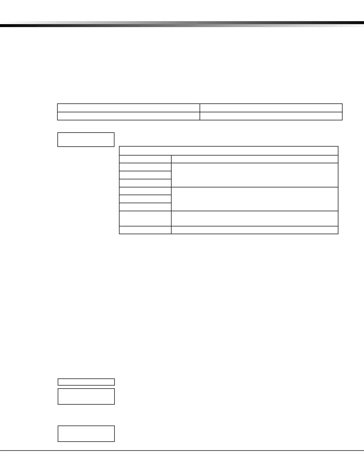
Wi-Fi Signal Strength (Wi-Fi SIGNAL)
This option tests the signal strength of the selected SSID. Press any select key or
area to display Wi-Fi signal strength. The
▐
’s represent the signal strength 0-7.
Wi-Fi Signal Strength
Number of Bars Indication
7
Good Signal (Excellent for consistent operation)6
5
4
Average Signal (Expect consistent operation)3
2
1 Weak Signal (Will not operate reliably. Relocate Wi-Fi
equipment or add a Wi-Fi extender for better reception.)
0 No Signal
Email Status
The Email Status menu tests each component of the panel’s e-mail communication. The test proceeds
until the rst component failure or until all components have been tested with positive results. The test
screen displays after each component for two seconds or until the CMD key has been pressed.
Panel Settings
Pressing a select key displays the MAC Address, Serial Number, Frequency Offset, Panel Model, and
Firmware Version.
MAC Address
Short for Media Access Control address. This hardware address uniquely identies each network node. Not
to be confused with an IP address, which is assignable. The MAC address is the panel on-board network
hardware address. Press any select key or area to display the panel MAC address.
Serial Number
This number is the network communicator serial number. Reference this number for communicator date-
of-manufacture, hardware version, etc. Press any select key or area to display the Serial Number.
Panel Number
This menu option displays the model number of the panel. The display will show XT30 or XT50 followed by
1-3 letters to indicate the communication type: C=Cellular, D=Dialer, N=Network.
Firmware Version
This menu option displays the Firmware Version number of the panel and date it was released.
Z-Wave Test Option
This feature allows the installer to test panel communication with Z-Wave devices.
A successful test indicates a response from a device. Press any select key or area to
view the Z-Wave Device List.
• Press COMMAND to advance through each Z-Wave device and press any select
key or area to begin the test on the device displayed.
• The name of the device displays above the device number. The current number
of successful communications followed by the total number of attempts
displays to the right of the device number. The test stops after 99 attempts.
Press COMMAND to view the nal number of successful communications.
SIGNAL
▐▐▐▐▐▐▐
HOMENET123
TEST ZWAVE
DEVICE LIST:
HALLWAY LIGHT
HALLWAY LIGHT
99/99 SUCCESSFUL