Engine
Systems
- Flow Diagrams
Page
OD-2
Lubrication and Maintenance
DODGE
TUrbo Diesel
Engine
Diagrams
The following drawings depict flow the various engine
systems.
A knowledge of the
systems
can help you
with
troubleshooting and general engine maintenance.
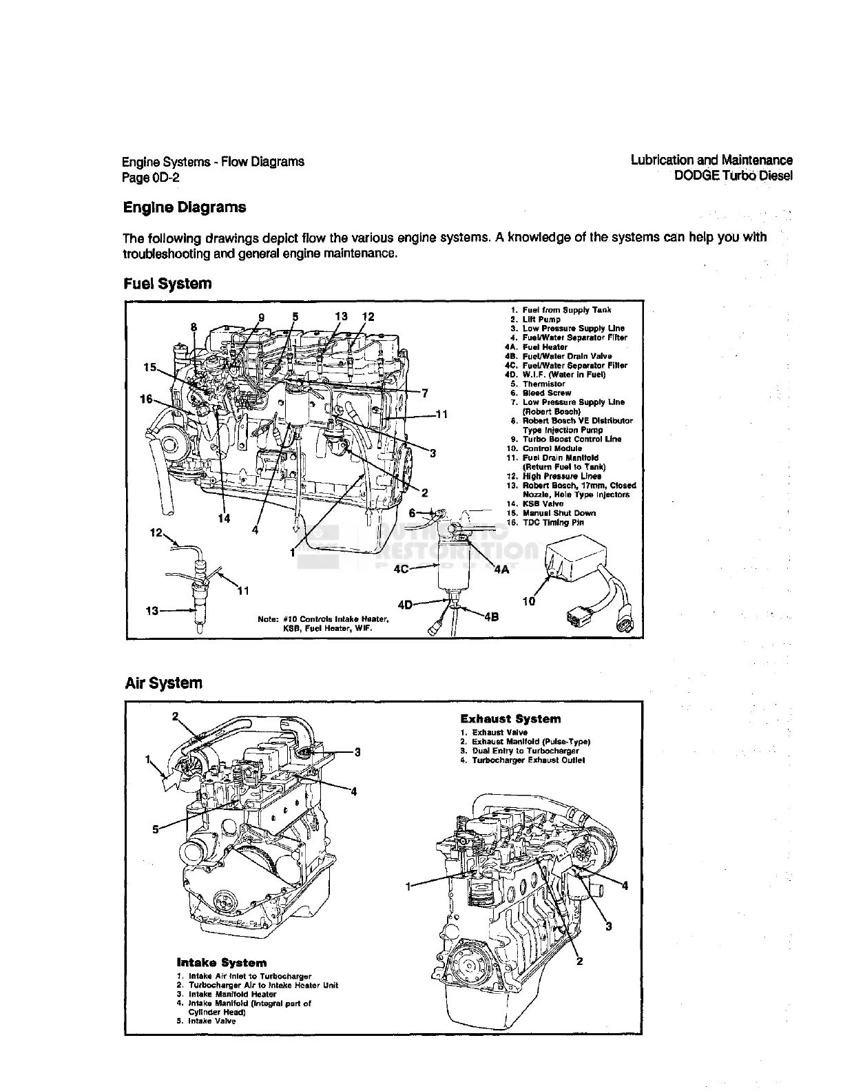
Fuel
System
Fuel
from
Supply Tank
Lift Pump
Low
Pressure Supply Line
Fuel/Water Separator Filter
Fuel
Heater
Fuel/Water Drain Valve
Fuel/Water Separator Filter
W.I.F. (Water in Fuel)
Thermistor
Bleed
Screw
Low
Pressure
Supply Line
(Robert
Bosch)
Robert
Bosch
VE Distributor
Type Injection Pump
Turbo Boost Control Line
Control
Module
Fuel
Drain
Manifold
(Return Fuel to Tank)
High Pressure
Lines
Robert
Bosch,
17mm, Closed
Nozzle, Hole Type Injectors
KSB
Valve
Manual Shut Down
TDC
Timing Pin
Air System
Intake System
1. Intake Air Inlet to Turbocharger
2. Turbocharger Air to Intake Heater Unit
3. Intake
Manifold
Heater
4. Intake
Manifold
(Integral part of
Cylinder
Head)
5. Intake Valve
Exhaust
System
1. Exhaust Valve
2. Exhaust
Manifold
(Pulse-Type)
3. Dual Entry to Turbocharger
4. Turbocharger Exhaust Outlet