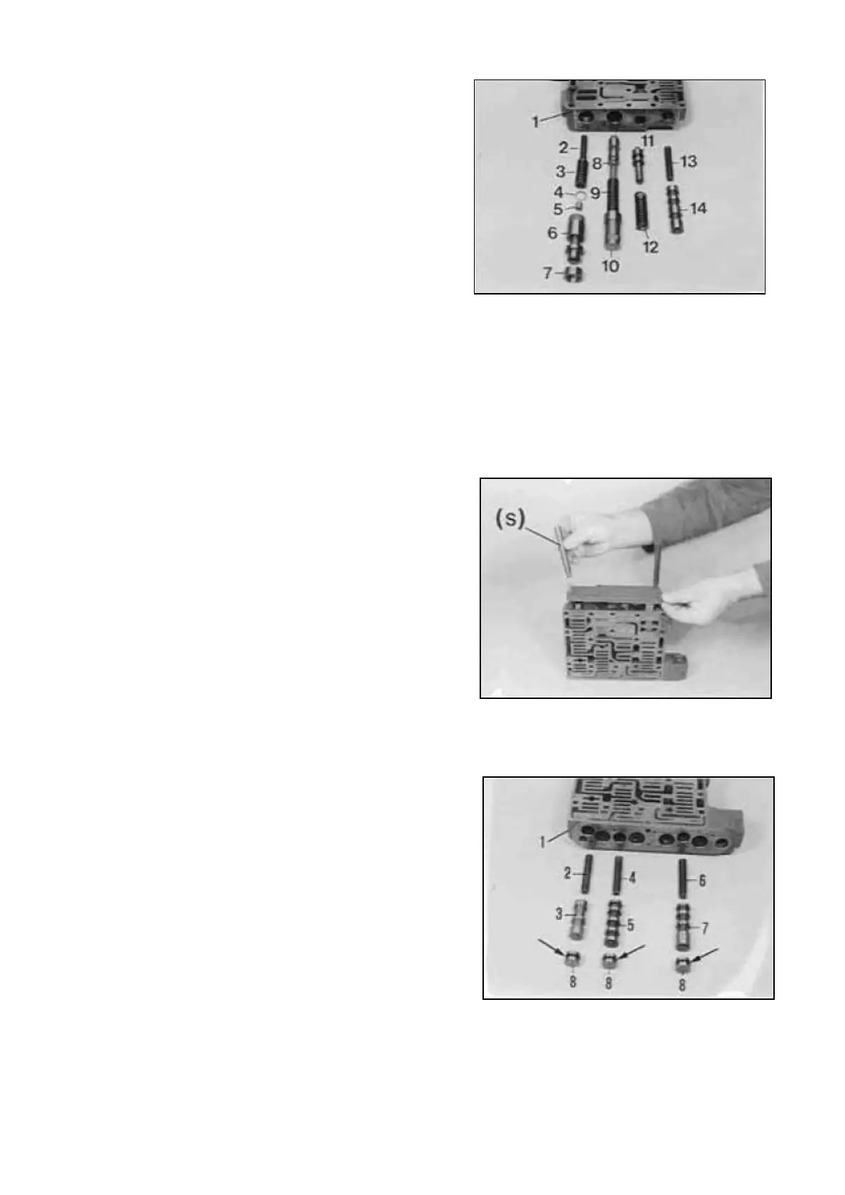
Install components :
1 = Valve body
2 = Spring (L = 88,6 mm)
3 = Spring (L = 52,0 mm)
1 = Disk (optional)
5 = Spacer
6 = Spool
7 = Sleeve
8 = Spool
9 = Spring (L =81,7 mm)
10 = Spool
11 = Spool
12 = Spring (L = 65,4 mm)
13 = Spring (L = 72,5 mm)
10 = Spool (total length 86,mm)
NOTE :
L= Length of the unloaded spring !
ps (control pressure) is determined by the disk (4)!
Pay attention to the General Instructions,
Page 12 ---14 !
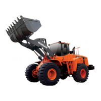
Install two adjusting screws ( S ) and mount flat
gasket.
Place cover against shoulder, using nuts ( S ).
Now, fasten cover by means of screws.
Torque limit (M5/8.8) 5,5 Nm
( S ) Adjusting screws (M5) 5870 204 036
with nut
( S ) Adjusting screws (M6) 5870 204 049
with nut
Install components :
1 = Valve body
2 = Spring ( L = 72,5 mm)
3 = Spool (3 control surfaces)
4 = Spring ( L = 72,5 mm)
5 = Spool (5 control surfaces)
6 = Spring ( L = 72,5 mm)
7 = Spool (total length 72,0 mm)
8 = Detent block (3 pieces)
NOTE :
Install new O-Rings, see Arrows !
Transmission and Torque Converter SPC000007
Page 19