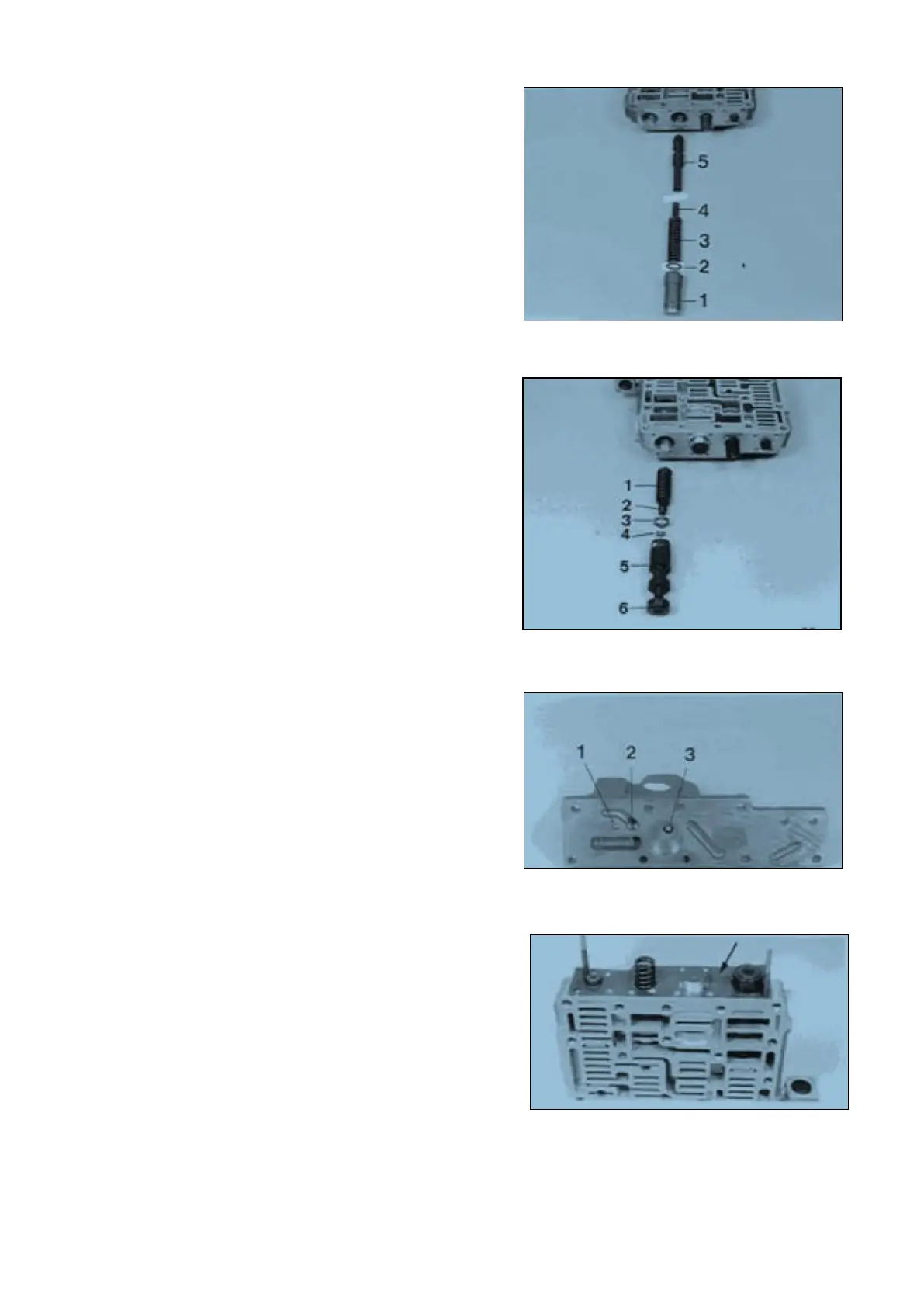
Pressure control valve :
Install components,
1 = Spool
2 = Disk (optional)
3 = Spring (L
0
= 76,70 mm)
4 = Spring (L
0
= 132,40 mm)
5 = Spool
NOTE ;
P1 is determined by the disk 2
(pay attention to Notes, Page 12 ... 14) !
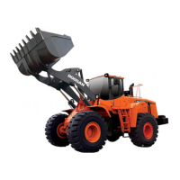
Control pressure valve :
Install components.
1 = Spring (L
0
= 65,40 mm)
2 = Spring (L
0
= 78,60 mm)
3 = Disk(s) (optional)
4 = Disk(s) (optional)
5 = Spool
6 = Sleeve
NOTE
P5 is determined by the disks 3 and 4
(pay attention to Notes, Page 12 ... 14) !
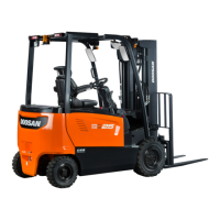
Pre-assemble and attach shift-control housing (WK)
(Figure 89 ... 92)
Close the two bores by means of balls and install
diaphragm.
1 = Bail (Φ 4,50 mm)
2 = Diaphragm (optional)
3 = Ball (Φ 7,00 mm)
NOTE :
Secure diaphragm by means of Loctite (Type No.
270) !
Now, clean diaphragm from Loctite residues by
means of compressed air I
t2 (Modulation time-WK) is determined by the
diaphragm 2
(pay attention to Notes Page 12 ... 14) !
Install two adjusting screws ( S ) and mount gasket
(Arrow).
( S ) Adjusting screws (M5) 5870 204 036
with nut
( S ) Adjusting screws (M6) 5870 204 049
with nut
SPC000007 Transmission and Torque Converter
Page 40