Pull shift-control housing by means of threaded
bushings ( S ) against shoulder.
Now, fasten lousing by means of socket head
screws.
Torque limit (M5/8.8) 5,5 Nm
( S ) Adjusting screws (M5) 5870 204 036
with nut
( S ) Adjusting screws (M6) 5870 204 049
with nut
Install components :
1 = Shift-control housing
2 = O-Ring
3 = Solenoid valve
4 = Socket head screws (with spring washer)
5= Spring( L
0
= 53,40 mm)
6 = Disk(s) (optional)
7 = Spool
8 = Screw plug (with O-Ring)
NOTE:
p2 is determired by the disk 6
(pay attention to Notes, Page 12 ... 14) I
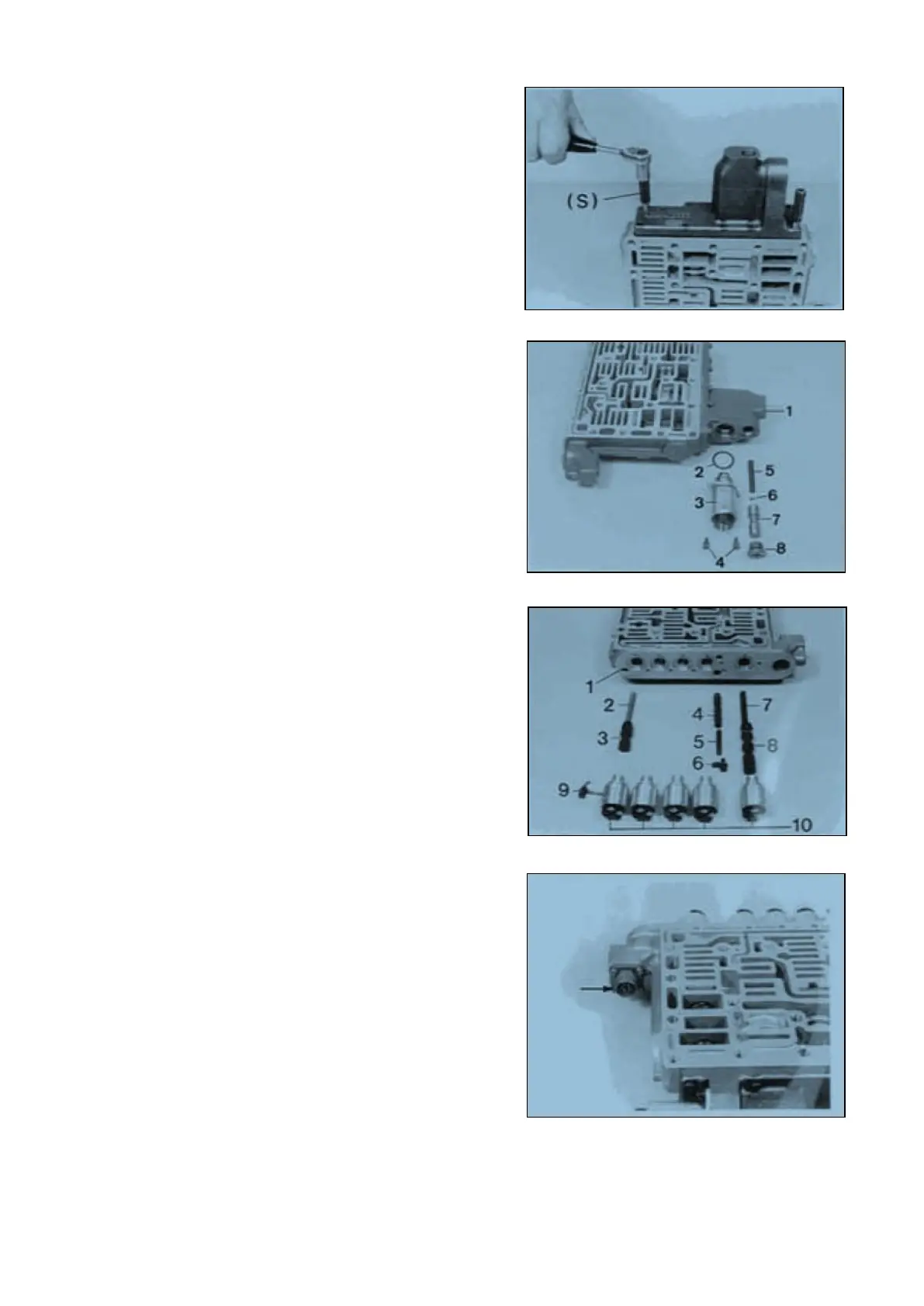
Install components :
1 = Shift-control housing
2 = Spring (Lo =51,30 mm)
3 = Spool
4 = Spool
5 = Spring (Lo =37,10 mm)
6 = Spool fixing (retaining plate and socket head
screw)
7 = Spring (Lo = 53,40 mm)
8 = Spool
9 = Retaining plate and socket head screw
10 = Solenoid valves (5x)
NOTE :
Pay attention to the installation position of the
solenoid valves, see Figure 95 !
Install cable harness.
NOTE :
Mount new gaskets 1
Pay attention to the location of the plug nose see
Arrow !
Transmission and Torque Converter SPC000007
Page 41