Install two adjusting screws ( S ) and assemble fat
gasket (Arrow).
Now, pull cover against shoulder, using nuts ( S )
and fix it provisionally by means of socket head
screws (4 pieces, see Figure 118).
( S ) Adjusting screws (M6) 5870 204 049
with nut
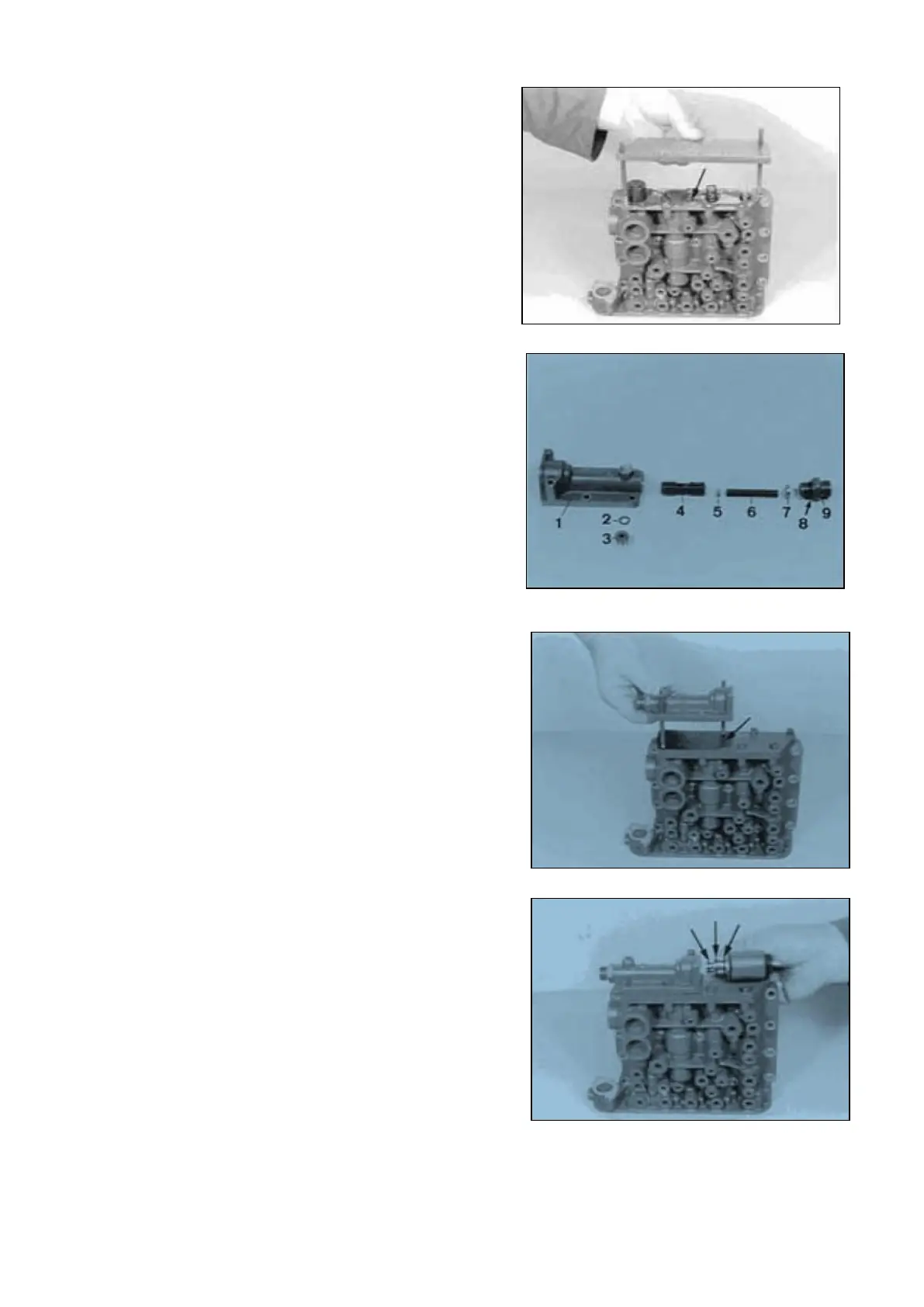
WK-Valve :
Install components.
1 = Shift-control housing
2 = O-Ring
3 = Screw plug
4 = Spool
5 = Disks (optional)
6 = Spring (Lo = 53,40 mm)
7 = Detent block (spring guide)
8 = O-Ring
9 = Connecting piece
NOTE :
Install detent block 7 with the countersinking facing
the spring !
p2 is determined by the disk 5
(pay attention to Notes, Page 12 ... 14 !
Install two adjusting screws and assemble flat
gasket (Arrow).
Fasten shift-control housing and cover by means of
socket head screws (mount flat washers).
Torque limit (M6/8.8) 9,5 Nm
( S ) Adjusting screws (M6) 5870 204 049
with nut
Mount new O-Rings (Arrows) and fasten solenoid
valve by means of socket head screws (mount flat
washers).
Torque limit (M5/8.8) 5,5 Nm
SPC000007 Transmission and Torque Converter
Page 50