3.2.4 Pre-assemble and install
countershaft assembly
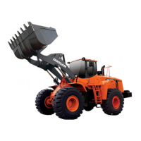
The illustration on the left shows the components.
1 = Closing cover
2 = Socket head screw
3 = O-Ring (installation position, see Arrow)
4 = Axle
5 = Shim
6 = Roller bearing
7 = Spur gear
NOTE :
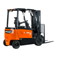
The countershaft gear is marked on the end face. In
the installed condition, the marking must be facing
the drive side (upwards).
Insert shim and pre-assembled spur gear (Figure
163).
NOTE :
Pay attention to the installation position of the collar
shim (Arrow) - radius on the inner diameter must
show upwards !
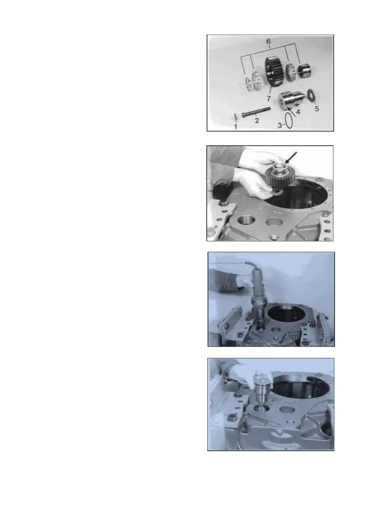
Heat bearing bores and bearing inner race (about
90° C).
( S ) Hot-air blower 220 V 5870 221 500
( S ) Hot-air blower 110 V 5870 221 501
Insert axle until contact is obtained.
SPC000007 Transmission and Torque Converter
Page 130
 Loading...