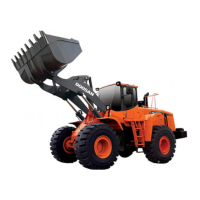
NOTE ;
To ensure an exact sealing of the suction ports and
pressure ports, resp. to avoid the breaking away of
the Loctite, fix oil supply flange by a provisional
installation of the two outer roll pins (10x50 mm) as
well as hex. head screws (3 pieces) radially and
axially, see Figure 259 ! The inner roll pins (6x50
mm) arc installed only after the attachment of the
engine connecting case (Figure 262).
Hardening time of the Loctite about 10…30 minutes.
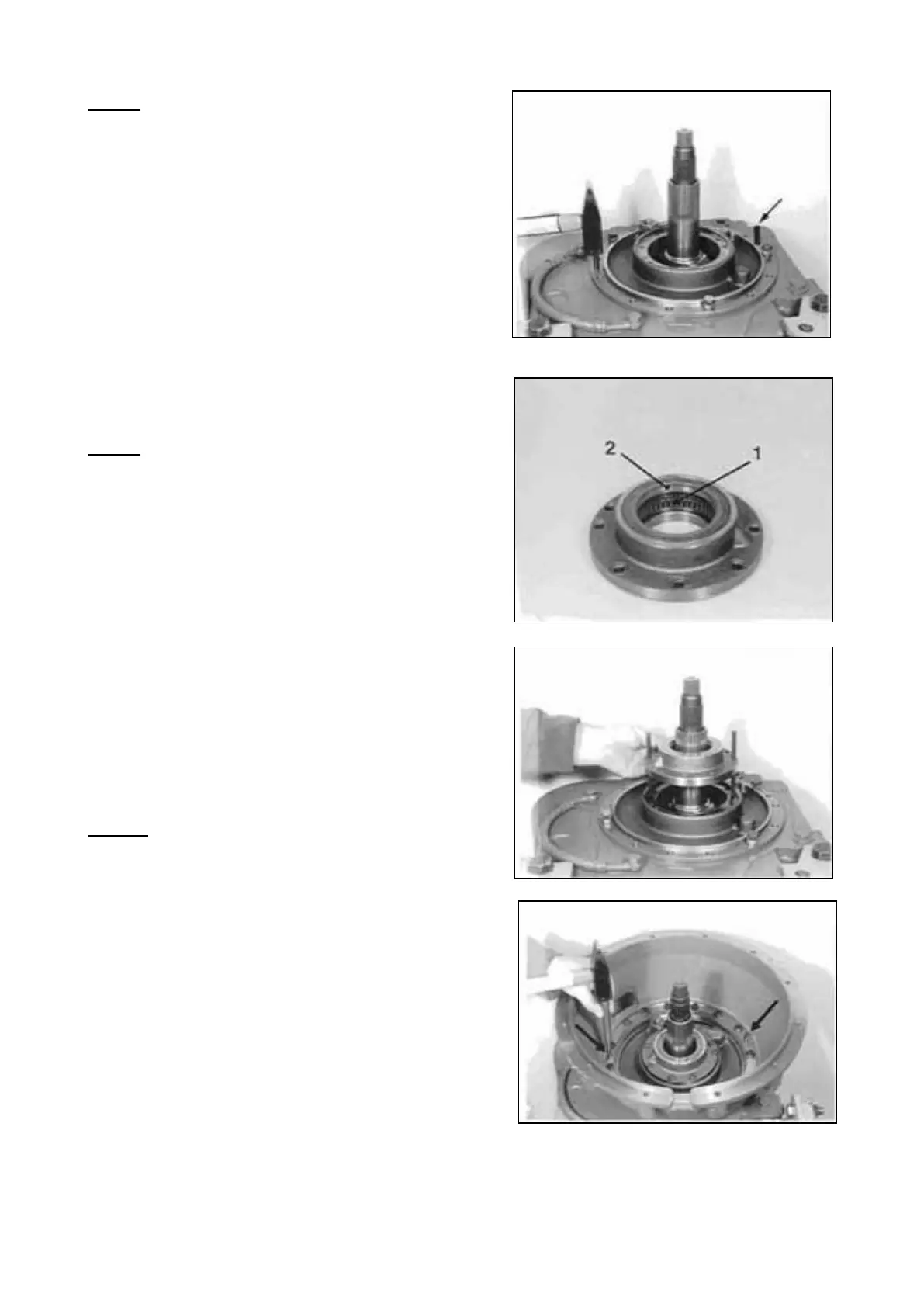
3.2.11 Engine connection
Install needle bearing (1) and shaft seal (2).
NOTE :
The needle bush is marked on one end face.
At the pressing in, the marking must be facing the
drift (upwards) !
The exact installation position is obtained by
application of the prescribed Special Tool.
Wet shaft seal outer diameter with sealing
compound !
( S ) Driver 5870 058 058
( S ) Driver 5870 055 022
( S ) Handle 5870 260 002
Install two adjusting screws and mount flat gasket.
Assemble bearing cap and fasten it by means of
hex. head screws.
Torque limit (M8/8.8) 23 Nm
NOTE ;
Pay attention to the radial installation position!
( S ) Adjusting screws (M8) 5870 204 011
Fasten engine connecting case by means of hex.
head screws and mount the two inner roll pins (6x50
mm).
Torque limit (Ml0/10.9) 68 Nm
SPC000007 Transmission and Torque Converter
Page 158
 Loading...